Jeep Cherokee owners,service,repair manuals & guides

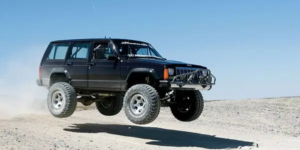
When the original Jeep Cherokee debuted back in 1984, its compact dimensions, unibody (as opposed to truck-based body-on-frame) architecture and go-anywhere capability made it an immediate success. But the SUV scene changed dramatically over the course of its nearly 20-year production run. By the early 2000s, car-based crossovers like the Honda CR-V and Toyota RAV4 had usurped the antiquated Cherokee's throne. With the arrival of the modernized Jeep Liberty for the 2002 model year, the Cherokee was put out to pasture, its time seemingly come and gone.
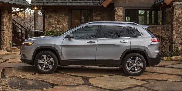
Aiming to be more than another run-of-the-mill crossover, the Cherokee brings a measure of ruggedness to the party in the way only a Jeep can. A standard 184-hp 2.4-liter four or optional 271-hp 3.2-liter V-6 each team with a nine-speed automatic. Front-wheel drive is standard; four-wheel drive is optional. Cargo capacity is simply average, but the interior is comfortable and well appointed. A more capable Trailhawk model should appeal to outdoorsy types and can tackle more serious terrain.

Jeep Cherokee (KL) 2014 - 2023 Owners Manual
Jeep Cherokee (XJ) 1984 - 2001 Service Manual
- Lubrication and maintenance
- Suspension
- Differential and driveline
- Brakes
- Clutch
- Cooling system
- Battery
- Starting systems
- Charging system
- Ignition system
- Instrument panel systems
- Audio systems
- Horn systems
- Speed control system
- Turn signal and hazard warning systems
- Wiper and washer systems
- Lamps
- Passive restraint systems
- Electrically heated systems
- Power distribution systems
- Power lock systems
- Vehicle theft/security systems
- Power seat systems
- Power window systems
- Power mirror systems
- Chime/buzzer warning systems
- Overhead console systems
- Engine
- Exhaust system
- Frame and bumpers
- Frame
- Fuel system
- Steering
- Transmission and transfer case
- Tires and wheels
- Body
- Heating and air conditioning
- Emission control systems