Jeep Cherokee (XJ): Steering linkage
STEERING LINKAGE DESCRIPTION The steering linkage consist of a pitman arm, drag
link, tie rod, tie rod ends and a steering damper (Fig.
1) and (Fig. 2). The service procedures and torque
specifications are the same for LHD and RHD vehicles.
CAUTION: Components attached with a nut and
cotter pin must be torqued to specification. Then if
the slot in the nut does not line up with the cotter
pin hole, tighten nut until it is aligned. Never loosen
the nut to align the cotter pin hole.
1 - PITMAN ARM
1 - PITMAN ARM STEERING LINKAGE The tie rod end and ball stud seals should be
inspected during all oil changes. If a seal is damaged,
it should be replaced. Before installing a new seal,
inspect ball stud at the throat opening. Check for
lubricant loss, contamination, ball stud wear or corrosion.
If these conditions exist, replace the tie rod. A
replacement seal can be installed if lubricant is in
good condition. Otherwise, a complete replacement
ball stud end should be installed.
CAUTION: If any steering components are replaced
or serviced an alignment must be performed, to
ensure the vehicle meets all alignment specifications.
CAUTION: Components attached with a nut and
cotter pin must be torqued to specification. Then if
the slot in the nut does not line up with the cotter
pin hole, tighten nut until it is aligned. Never loosen
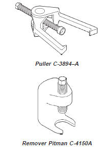
the nut to align the cotter pin hole. CAUTION: Use a Puller tool C-3894-A for tie rod
removal. Failure to use this tool could damage the
ball stud and seal (Fig. 3). REMOVAL (1) Remove the cotter pins and nuts at the tie rod
ball studs and drag link.
(2) Loosen the ball studs with a puller tool to
remove the tie rod.
(3) Loosen clamp bolts and unthread the tie rod
end from the tube. INSTALLATION (1) Thread the tie rod end into the tube and position
the clamp to it's original position (Fig. 4).
Tighten the clamp bolts to 27 N·m (20 ft. lbs.).
(2) Install the tie rod on the drag link and steering
knuckle. Install the retaining nuts.
(3) Tighten the ball stud nut on the steering
knuckle to 47 N·m (35 ft. lbs.). Tighten the ball stud
nut to drag link to 74 N·m (55 ft. lbs.). Install new
cotter pins.
1 - CLAMP
1 - TIE ROD CLAMP REMOVAL (1) Remove the cotter pin and nut from the drag
link at the pitman arm.
(2) Remove the drag link ball stud from the pitman
arm with a puller.
(3) Remove the nut and washer from the steering
gear shaft. Mark the pitman shaft and pitman arm
for installation reference. Remove the pitman arm
from steering gear with Puller C-4150-A (Fig. 5).
1 - PITMAN ARM INSTALLATION (1) Align and install the pitman arm on steering
gear shaft.
(2) Install the washer and nut on the shaft and
tighten nut to 251 N·m (185 ft. lbs.).
(3) Install drag link ball stud to pitman arm
install nut and tighten to 74 N·m (55 ft. lbs.). Install
a new cotter pin. REMOVAL (1) Remove cotter pins and nuts from drag link
(2) Remove the steering damper ball stud from the
drag link.
(3) Remove tie rod from drag link
(4) Remove drag link from the steering knuckle
and pitman arm. INSTALLATION (1) Install the drag link onto steering knuckle and
pitman arm.
(2) Install nut at steering knuckle and tighten to
47 N·m (35 ft. lbs.). Install new cotter pins.
(3) Install nut at pitman arm and tighten to 74
N·m (55 ft. lbs.). Install new cotter pins.
(4) Install tie rod onto drag link and install nut.
Tighten nut to 74 N·m (55 ft. lbs.) and install new
cotter pins. (5) Install steering damper onto drag link and
install nut. Tighten nut to 74 N·m (55 ft. lbs.) and
install a new cotter pin. REMOVAL (1) Remove the steering damper retaining bolt
from the axle bracket.
(2) Remove the cotter pin and nut from the ball
stud at the drag link.
(3) Remove the steering damper ball stud from the
drag link with Puller C-3894-A. INSTALLATION (1) Install steering damper onto the axle bracket
and drag link.
(2) Install steering damper bolt in axle bracket
and tighten nut to 75 N·m (55 ft. lbs.).
(3) Install ball stud nut at the drag link and
tighten nut to 75 N·m (55 ft. lbs.). Install a new cotter
pin. TORQUE CHART DESCRIPTION TORQUE Pitman Arm Shaft . . . . . . . . . . . . . . . . . 251 N·m (185 ft. lbs.) Drag Link Ball Studs . . . . . . . . . . . . . . . 74 N·m (55 ft. lbs.) Tie Rod Ends Ball Studs . . . . . . . . . . . . . . . 74 N·m (55 ft. lbs.) Tie Rod Ball Stud . . . . . . . . . . . . . . . . 47 N·m (35 ft. lbs.) Steering Damper Frame . . . . . . . . . . . . . . . . . . 74 N·m (55 ft. lbs.) STEERING LINKAGE
Description and operation
Fig. 1 Steering Linkage-LHD
2 - ADJUSTMENT SLEEVE
3 - DRAG LINK
4 - TIE ROD
5 - STEERING DAMPENER
Fig. 2 Steering Linkage-RHD
2 - DRAG LINK
3 - STEERING DAMPNER
4 - TIE ROD
5 - ADJUSTMENT SLEEVEService procedures
Removal and installation
Tie rod
Fig. 3 Ball Stud Puller
2 - ADJUSTMENT SLEEVE
3 - PULLER TOOL C-3894-A
4 - SEAL
5 - TIE-ROD END
Fig. 4 Tie Rod/Drag Link Clamps
2 - DRAG LINK CLAMPSPitman ARM
Fig. 5 Pitman Arm Puller
2 - SPECIAL TOOL C-4150-A
3 - WRENCHDrag link
Steering damper
Specifications
Clamp . . . . . . . . . . . . . . . . . . 49 N·m (36 ft. lbs.)
Clamp . . . . . . . . . . . . . . . . . . 27 N·m (20 ft. lbs.)
Drag Link . . . . . . . . . . . . . . . 74 N·m (55 ft. lbs.)Special tools


Other materials:
Diagnosis and testing. Removal and installation
Diagnosis and testing
Low lubricant level
A low transmission lubricant level is generally the
result of a leak, inadequate lubricant fill, or an incorrect
lubricant level check.
Leaks can occur at the mating surfaces of the gear
case, intermediate plate and adaptor or extension
housing, or fr ...