Jeep Cherokee owners,service,repair manuals & guides
When the original Jeep Cherokee debuted back in 1984, its compact dimensions, unibody (as opposed to truck-based body-on-frame) architecture and go-anywhere capability made it an immediate success. But the SUV scene changed dramatically over the course of its nearly 20-year production run. By the early 2000s, car-based crossovers like the Honda CR-V and Toyota RAV4 had usurped the antiquated Cherokee's throne. With the arrival of the modernized Jeep Liberty for the 2002 model year, the Cherokee was put out to pasture, its time seemingly come and gone.
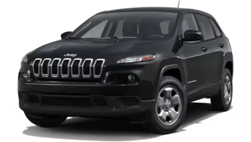
Aiming to be more than another run-of-the-mill crossover, the Cherokee brings a measure of ruggedness to the party in the way only a Jeep can. A standard 184-hp 2.4-liter four or optional 271-hp 3.2-liter V-6 each team with a nine-speed automatic. Front-wheel drive is standard; four-wheel drive is optional. Cargo capacity is simply average, but the interior is comfortable and well appointed. A more capable Trailhawk model should appeal to outdoorsy types and can tackle more serious terrain.

Jeep Cherokee (KL) 2014 - 2023 Owners Manual
Owners Manual for third generation of Jeep Cherokee, model years 2014 - 2023. The third-generation Cherokee was the most significant departure from traditional Cherokee styling ever. The compact SUV’s bodystyle featured smooth lines, consistent with other modern SUVs, and did not subtract from the Cherokee's off-road capabilities.

Jeep Cherokee (XJ) 1984 - 2001 Service Manual
Service Manual for second generation of Jeep Cherokee, model years 1984 - 2001. The second-generation Cherokee “XJ“is perhaps the most widely-known and most famous Jeep model to date, aside from the Jeep Wrangler, as it was considered instrumental in the historical development of 4x4 SUV.