Jeep Cherokee (XJ): Accumulator. Blower motor. Blower motor relay
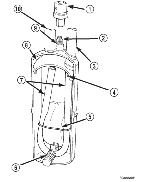
DESCRIPTION The accumulator is mounted in the engine compartment
between the evaporator coil outlet tube and
the compressor inlet. OPERATION Refrigerant enters the accumulator canister as a
low pressure vapor through the inlet tube. Any liquid,
oil-laden refrigerant falls to the bottom of the
canister, which acts as a separator. A desiccant bag is
mounted inside the accumulator canister to absorb
any moisture which may have entered and become
trapped within the refrigerant system (Fig. 1).
1 - LOW PRESSURE CYCLING CLUTCH SWITCH DESCRIPTION The blower motor and blower wheel are located in
the passenger side end of the heater-A/C housing,
below the glove box. The blower motor controls the
velocity of air flowing through the heater-A/C housing
by spinning a squirrel cage-type blower wheel
within the housing at the selected speed. The blower
motor and wheel can be removed through an opening
in the engine compartment side of the dash panel
without heater-A/C housing removal. OPERATION The blower motor will only operate when the ignition
switch is in the On position, and the heater-A/C
mode control switch knob is in any position, except
Off. The blower motor receives a fused battery feed
through the blower motor relay whenever the ignition
switch is in the On position. The blower motor
battery feed circuit is protected by a fuse in the
Power Distribution Center (PDC). Blower motor
speed is controlled by regulating the ground path
through the heater-A/C control blower motor switch
and the blower motor resistor.
The blower motor and blower motor wheel cannot
be repaired and, if faulty or damaged, they must be
replaced. The blower motor and blower wheel are serviced
only as a unit. DESCRIPTION The blower motor relay is a International Standards
Organization (ISO)-type relay. The relay is a
electromechanical device that switches battery current
from a fuse in the Power Distribution Center
(PDC) directly to the blower motor. The relay is energized
when the relay coil is provided a voltage signal
by the ignition switch. See Blower Motor Relay in the
Diagnosis and Testing section of this group for more
information. OPERATION The blower motor relay is installed in a wire harness
connector that is secured to the passenger side
outboard end of the heater-A/C housing in the passenger
compartment, next to the heater-A/C wire
harness connector.
The blower motor relay cannot be repaired and, if
faulty or damaged, it must be replaced.Accumulator

Fig. 1 Accumulator - Typical
2 - PRESSURE SWITCH FITTING
3 - OUTLET TO COMPRESSOR
4 - ANTI-SIPHON HOLE
5 - DESICCANT BAG
6 - OIL RETURN ORIFICE FILTER
7 - VAPOR RETURN TUBE
8 - ACCUMULATOR DOME
9 - O-RING SEAL
10 - INLET FROM EVAPORATORBlower motor
Blower motor relay
 Blower motor resistor. Blower motor switch. Compressor
Other materials:
Towing This Vehicle Behind Another Vehicle. Recreational Towing - Front-Wheel Drive (FWD) Models. Recreational Towing - 4X4 Models With 1-Speed
Power Transfer Unit
Towing This Vehicle Behind Another Vehicle
4X4 Models
Towing Condition
Wheels OFF the
Ground
Front-Wheel Drive
(FWD) Models
1-Speed Power
Transfer Unit
2-Speed Power
Transfer Unit
Flat Tow
NONE
NOT ALLOWED
NOT ALLOWED
See Instruc ...

