Jeep Cherokee (XJ): Compressor clutch relay. Condenser. Dual function high pressure switch/high pressure cut-off switch
(1) Disconnect and isolate the battery negative
cable.
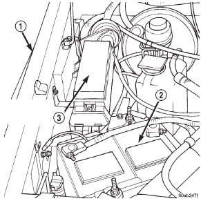
(2) Remove the cover from the Power Distribution
Center (PDC) (Fig. 30).
(3) Refer to the label on the PDC for compressor
clutch relay identification and location.
(4) Unplug the compressor clutch relay from the
PDC.
(5) Install the compressor clutch relay by aligning
the relay terminals with the cavities in the PDC and
pushing the relay firmly into place.
(6) Install the PDC cover.
(7) Connect the battery negative cable.
(8) Test the relay operation.
1 - RIGHT FENDER WARNING: REVIEW THE WARNINGS AND CAUTIONS
IN THE FRONT OF THIS GROUP BEFORE
PERFORMING THE FOLLOWING OPERATION.
CAUTION: Before removing the condenser, note the
location of each of the radiator and condenser air
seals. These seals are used to direct air through the
condenser and radiator. The air seals must be reinstalled
in their proper locations in order for the air
conditioning and engine cooling systems to perform
as designed. REMOVAL (1) Disconnect and isolate the battery negative
cable.
(2) Recover the refrigerant from the refrigerant
system. See Refrigerant Recovery in this group for
the procedures.
(3) Disconnect the discharge line refrigerant line
fitting at the condenser inlet. See Refrigerant Line
Coupler in this group for the procedures. Install
plugs in, or tape over all of the opened refrigerant
line fittings.
(4) Disconnect the liquid line (Left-Hand Drive) or
liquid line jumper (Right-Hand Drive) refrigerant
line fitting at the condenser outlet. See Refrigerant
Line Coupler in this group for the procedures. Install
plugs in, or tape over all of the opened refrigerant
line fittings.
(5) Remove the radiator and the condenser from
the vehicle as a unit. Refer to Group 7 - Cooling System
for the procedures.
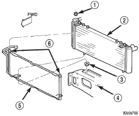
(6) Remove the two nuts that secure the condenser
studs to the upper brackets of the radiator (Fig. 31).
1 - NUT (7) Slide the condenser down from the radiator far
enough for the condenser studs to clear the upper
radiator bracket holes, and for the lower condenser
bracket holes to clear the dowel pins on the bottom of
the radiator.
(8) Remove the condenser from the radiator. INSTALLATION (1) Install the holes of the condenser lower brackets
over the dowel pins on the bottom of the radiator.
(2) Slide the condenser upwards until both of the
condenser studs are installed through the holes in
the radiator upper brackets. Tighten the mounting
nuts to 5.3 N·m (47 in. lbs.).
(3) Renstall the radiator and condenser unit in the
vehicle. Refer to Group 7 - Cooling System for the
procedures.
(4) Remove the tape or plugs from the refrigerant
line fittings on the condenser outlet and the liquid
line (Left-Hand Drive) or the liquid line jumper
(Right-Hand Drive). Install the liquid line or the liquid line jumper to the
condenser outlet. See Refrigerant
Line Coupler in this group for the procedures.
(5) Remove the tape or plugs from the refrigerant
line fittings on the condenser inlet and the discharge
line. Connect the discharge line to the condenser
inlet. See Refrigerant Line Coupler in this group for
the procedures.
(6) Connect the battery negative cable.
(7) Evacuate the refrigerant system. See Refrigerant
System Evacuate in this group for the procedures.
(8) Charge the refrigerant system. See Refrigerant
System Charge in this group for the procedures.
NOTE: If the condenser is replaced, add 30 milliliters
(1 fluid ounce) of refrigerant oil to the refrigerant
system. Use only refrigerant oil of the type
recommended for the compressor in the vehicle. REMOVAL (1) Disconnect and isolate the battery negative
cable.
(2) Unplug the wire harness connector from the
dual function high pressure switch or the high pressure
cut-off switch, which is mounted to a fitting on
the non-flexible section of the discharge line nearest
the compressor.
(3) Unscrew the high pressure switch from the discharge
line fitting.
(4) Remove the high pressure switch from the
vehicle.
(5) Remove the O-ring seal from the discharge line
fitting and discard. INSTALLATION (1) Lubricate a new O-ring seal with clean refrigerant
oil and install it on the discharge line fitting.
Use only the specified O-rings as they are made of a
special material for the R-134a system. Use only
refrigerant oil of the type recommended for the compressor
in the vehicle.
(2) Install and tighten the high pressure switch on
the discharge line fitting.
(3) Plug the wire harness connector into the high
pressure cut-off switch.
(4) Connect the battery negative cable.Compressor clutch relay

Fig. 30 Power Distribution Center
2 - BATTERY
3 - POWER DISTRIBUTION CENTERCondenser

Fig. 31 Condenser Remove/Install
2 - RADIATOR
3 - GROMMET
4 - LOWER CROSSMEMBER
5 - CONDENSER
6 - STUDSDual function high pressure
switch/high pressure cut-off
switch
Other materials:
Passenger side airbag door. Airbag control module. Clockspring
Passenger side airbag door
WARNING:
THE AIRBAG SYSTEM IS A SENSITIVE, COMPLEX
ELECTROMECHANICAL UNIT. BEFORE
ATTEMPTING TO DIAGNOSE OR SERVICE ANY AIRBAG
SYSTEM OR RELATED STEERING WHEEL,
STEERING COLUMN, OR INSTRUMENT PANEL
COMPONENTS YOU MUST FIRST DISCONNECT
AND ISOLATE THE ...


