Jeep Cherokee (XJ): Compressor clutch relay. Dual function high pressure switch/high pressure cut-off switch. Heater performance
RELAY TEST The compressor clutch relay (Fig. 8) is located in
the Power Distribution Center (PDC). Refer to the
PDC label for relay identification and location.
Remove the relay from the PDC to perform the following
tests:
(1) A relay in the de-energized position should
have continuity between terminals 87A and 30, and
no continuity between terminals 87 and 30. If OK, go
to Step 2. If not OK, replace the faulty relay.
(2) Resistance between terminals 85 and 86 (electromagnet)
should be 75 6 5 ohms. If OK, go to Step
3. If not OK, replace the faulty relay.
(3) Connect a battery to terminals 85 and 86.
There should now be continuity between terminals
30 and 87, and no continuity between terminals 87A
and 30. If OK, see Relay Circuit Test in the Diagnosis
and Testing section of this group. If not OK,
replace the faulty relay. RELAY CIRCUIT TEST For circuit descriptions and diagrams, refer to
8W-42 - Air Conditioning/Heater in Group 8W - Wiring
Diagrams.
(1) The relay common feed terminal cavity (30) is
connected to fused battery feed. There should be battery
voltage at the cavity for relay terminal 30 at all
times. If OK, go to Step 2. If not OK, repair the open
circuit to the fuse in the PDC as required.
(2) The relay normally closed terminal (87A) is not
used in this application. Go to Step 3.
(3) The relay normally open terminal cavity (87) is
connected to the compressor clutch coil. There should
be continuity between this cavity and the A/C compressor
clutch relay output circuit cavity of the compressor clutch coil wire harness
connector. If OK, go
to Step 4. If not OK, repair the open circuit as
required.
(4) The relay coil battery terminal (86) is connected
to the fused ignition switch output (run/start)
circuit. There should be battery voltage at the cavity
for relay terminal 86 with the ignition switch in the
On position. If OK, go to Step 5. If not OK, repair the
open circuit to the fuse in the junction block as
required.
(5) The coil ground terminal cavity (85) is switched
to ground through the Powertrain Control Module
(PCM). There should be continuity between this cavity
and the A/C compressor clutch relay control circuit
cavity of the PCM wire harness connector C
(gray) at all times. If not OK, repair the open circuit
as required. Before performing diagnosis of the dual function
high pressure switch, or the high pressure cut-off
switch, verify that the refrigerant system has the correct
refrigerant charge. See Refrigerant System
Charge in the Service Procedures section of this
group for more information.
For circuit descriptions and diagrams, refer to
8W-42 - Air Conditioning/Heater in Group 8W - Wiring
Diagrams.
(1) Disconnect and isolate the battery negative
cable.
(2) Unplug the high pressure switch wire harness
connector from the switch on the refrigerant system
fitting.
(3) On the dual function high pressure switch,
check for continuity between terminals C and D. On
the two terminal switch, check for continuity
between both terminals of the high pressure cut-off
switch. There should be continuity. If OK, test and
repair the A/C switch sense circuit as required. If not
OK, replace the faulty switch. Before performing the following tests, refer to
Group 7 - Cooling System for the procedures to check
the radiator coolant level, serpentine drive belt tension,
radiator air flow and the radiator fan operation.
Also be certain that the accessory vacuum supply
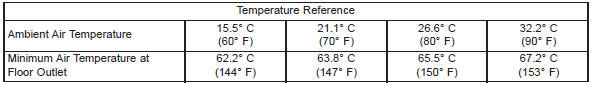
line is connected at the engine intake manifold. MAXIMUM HEATER OUTPUT Engine coolant is delivered to the heater core
through two heater hoses. With the engine idling at
normal operating temperature, set the temperature
control knob in the full hot position, the mode control
switch knob in the floor heat position, and the blower
motor switch knob in the highest speed position.
Using a test thermometer, check the temperature of
the air being discharged at the heater-A/C housing
floor outlets. Compare the test thermometer reading
to the Temperature Reference chart. If the floor outlet air temperature is too low, refer
to Group 7 - Cooling System to check the engine coolant
temperature specifications. Both of the heater
hoses should be hot to the touch. The coolant return
heater hose should be slightly cooler than the coolant
supply heater hose. If the return hose is much cooler
than the supply hose, locate and repair the engine
coolant flow obstruction in the cooling system. Refer
to Group 7 - Cooling System for the procedures.
OBSTRUCTED COOLANT FLOW Possible locations
or causes of obstructed coolant flow: If proper coolant flow through the cooling system is
verified, and heater outlet air temperature is still
low, a mechanical problem may exist.
MECHANICAL PROBLEMS Possible locations or
causes of insufficient heat: TEMPERATURE CONTROL If the heater outlet air temperature cannot be
adjusted with the temperature control knob on the
heater-A/C control panel, the following could require
service:Compressor clutch relay
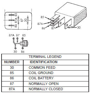
Fig. 8 Compressor Clutch RelayDual function high pressure
switch/high pressure cut-off
switch
Heater performance
 Blower motor switch. Compressor. Compressor clutch coil
 Low pressure cycling clutch switch. Refrigerant system leaks. Vacuum system
Other materials:
Wiper motor. Wiper switch and washer switch. Washer system
Wiper motor
FRONT
(1) Disconnect and isolate the battery negative
cable.
(2) Remove the wiper arms from the wiper pivots.
See Wiper Arm in this group for the procedures.
(3) Remove the eight screws that secure the cowl
plenum cover/grille panel and screen to the cowl top
panel (Fig. 9).
...