Jeep Cherokee (XJ): Description and operation
DESCRIPTION The 4.0 Liter (242 CID) six-cylinder engine is an
In-line, lightweight, overhead valve engine.
This engine is designed for unleaded fuel. The
engine cylinder head has dual quench-type combustion
chambers that create turbulence and fast burning
of the air/fuel mixture. This results in good fuel
economy.
The cylinders are numbered 1 through 6 from front
to rear. The firing order is 1-5-3-6-2-4 (Fig. 1).
The crankshaft rotation is clockwise, when viewed
from the front of the engine. The crankshaft rotates
within seven main bearings. The camshaft rotates
within four bearings. BUILD DATE CODE The engine Build Date Code is located on a
machined surface on the right side of the cylinder
block between the No.2 and No.3 cylinders (Fig. 2).
The digits of the code identify: (1) FOR EXAMPLE: Code * 801MX12 * identifies
a 4.0 Liter (242 CID) engine with a multi-point
fuel injection system, 8.7:1 compression ratio and
built on January 12, 1998.
1 - YEAR DESCRIPTION A gear-type positive displacement pump is
mounted at the underside of the block opposite the
No. 4 main bearing. OPERATION The pump draws oil through the screen and inlet
tube from the sump at the rear of the oil pan. The oil
is driven between the drive and idler gears and
pump body, then forced through the outlet to the
block. An oil gallery in the block channels the oil to
the inlet side of the full flow oil filter. After passing
through the filter element, the oil passes from the
center outlet of the filter through an oil gallery that
channels the oil up to the main gallery which
extends the entire length of the block.
Galleries extend downward from the main oil gallery
to the upper shell of each main bearing. The
crankshaft is drilled internally to pass oil from the
main bearing journals (except number 4 main bearing
journal) to the connecting rod journals. Each connecting
rod bearing cap has a small squirt hole, oil
passes through the squirt hole and is thrown off as
the rod rotates. This oil throwoff lubricates the camshaft
lobes, distributor drive gear, cylinder walls, and
piston pins.
The hydraulic valve tappets receive oil directly
from the main oil gallery. Oil is provided to the camshaft
bearing through galleries. The front camshaft
bearing journal passes oil through the camshaft sprocket to the timing chain.
Oil drains back to the
oil pan under the number one main bearing cap.
The oil supply for the rocker arms and bridged
pivot assemblies is provided by the hydraulic valve
tappets which pass oil through hollow push rods to a
hole in the corresponding rocker arm. Oil from the
rocker arm lubricates the valve train components,
then passes down through the push rod guide holes
in the cylinder head past the valve tappet area, and
returns to the oil pan.
1 - CAM/CRANK MAIN GALLERY (7) DESCRIPTION The cylinder block is a cast iron inline six cylinder
design. The cylinder block is drilled
1 - BLOCK DESCRIPTION The cylinder head is made of cast iron containing
twelve valves made of chrome plated heat resistant
steel, valve stem seals, springs, retainers and keepers.
The cylinder head and valve seats can be resurfaced
for service purposes.
The valve guides are integral to the cylinder head,
They are not replaceable. However, they are serviceable.
The cylinder head uses dual quench-type design
combustion chambers which cause turbulence in the
cylinders allowing faster burning of the air/fuel mixture,
resulting in better fuel economy (Fig. 4).
1 - CYLINDER HEAD BOLTS DESCRIPTION The crankshaft is constructed of nodular cast iron.
The crankshaft is a crosshaped four throw design
with eight counterweights for balancing purposes.
The crankshaft is supported by seven select main
bearings with the number three serving as the thrust
washer location. The main journals of the crankshaft
are cross drilled to improve rod bearing lubrication.
The select fit main bearing markings are located on
the crankshaft counter weights. The crankshaft rear
oil seal is a two piece design. The front oil seal is a
one piece design retained in the timing chain cover
(Fig. 5). 1 - 1/4" LETTERS DESCRIPTION The pistons are made of a high strength aluminum
alloy with an anodized top ring groove and crown.
Piston skirts are coated with a solid lubricant
(Molykote) to reduce friction and provide scuff resistance.
The connecting rods are made of ductile iron.
A pressed fit piston pin is used to attach the piston
and connecting rod.
DESCRIPTION The camshaft is made of gray cast iron with twelve
machined lobes and four bearing journals. When the
camshaft rotates the lobes actuate the tappets and
push rods, forcing upward on the rocker arms which
applies downward force on the valves. DESCRIPTION The rocker arms are made of stamped steel and
have a operational ratio of 1.6:1. When the push rods
are forced upward by the camshaft lobes the push
rod presses upward on the rocker arms, the rocker
arms pivot, forcing downward pressure on the valves
forcing the valves to move downward and off from
their seats (Fig. 8).
1 - CAMSHAFT
1 - CAPSCREWS DESCRIPTION The valves are made of heat resistant steel and
have chrome plated stems to prevent scuffing. All
valves use three bead locks to promote valve rotation
(Fig. 9).
1 - VALVE LOCKS (3-BEAD) Valve spring DESCRIPTION The valve springs are made of high strength silicon
chrome spring steel. The springs are common for
both intake and exhaust valves. (Fig. 9). DESCRIPTION The cylinder head cover (Fig. 10) is made of
stamped steel and incorporates the Crankcase Ventilation
(CCV) Hoses and the oil fill opening.
DESCRIPTION Valve lash is controlled by hydraulic tappets
located inside the cylinder block, in tappet bores
above the camshaft. Valve guide DESCRIPTION The valve guides are integral to the cylinder head,
They are not replaceable. However, they are serviceable. Oil pan DESCRIPTION The oil pan is made of stamped steel. The oil pan
gasket is a one piece steel backbone silicone coated
gasket. DESCRIPTION The valve stem seals are made of rubber and incorporate
a garter spring to maintain consistent lubrication
control (Fig. 9). Intake manifold DESCRIPTION The intake manifold is made of cast aluminum and
uses eleven bolts to mount to the cylinder head. This
mounting style improves sealing and reduces the
chance of leaks.
Fig. 11 Oil Pan 1 - OIL PAN
DESCRIPTION
The two exhaust manifolds are log style and are
made of high silicon molybdenum cast iron. The exhaust manifolds share a common
gasket with the
intake manifold. The exhaust manifolds also incorporate
ball flange outlets for improved sealing and
strain free connections.Engine
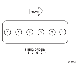
Fig. 1 Engine Firing Order
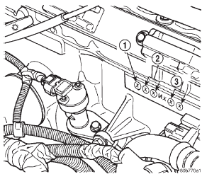
Fig. 2 Build Date Code Location
2 - MONTH
3 - DAYLubrication system
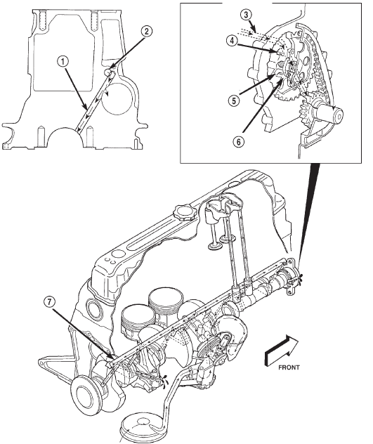
Oil Lubrication System-4.0L Engine
2 - TAPPET GALLERY
3 - TAPPET GALLERY
4 - CAMSHAFT BEARING
5 - NUMBER 1 CAMSHAFT BEARING JOURNAL
6 - CAMSHAFT SPROCKET
7 - TAPPET GALLERYCylinder block
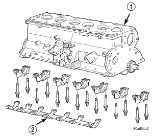
Fig. 3 4.0L Cylinder Block with Main Bearing Caps and Cap Brace
2 - MAIN BEARING CAP BRACECylinder head
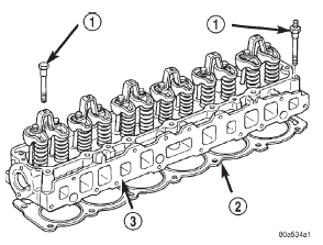
Fig. 4 Cylinder Head 4.0L Engine
2 - CYLINDER HEAD GASKET
3 - CYLINDER HEADCrankshaft
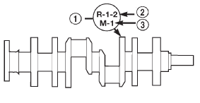
2 - (ROD)
3 - (MAIN)Piston and connecting rod
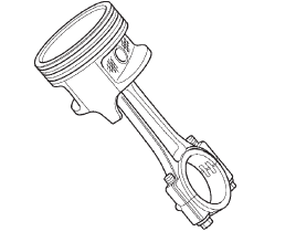
Fig. 6 Piston and Connecting Rod AssemblyCamshaft
Rocker ARM
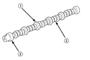
Fig. 7 Camshaft-Typical
2 - LOBES
3 - BEARING JOURNAL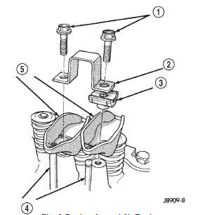
Fig. 8 Rocker Arms 4.0L Engine
2 - BRIDGE
3 - PIVOT ASSEMBLY
4 - PUSH RODS
5 - ROCKER ARMSValves
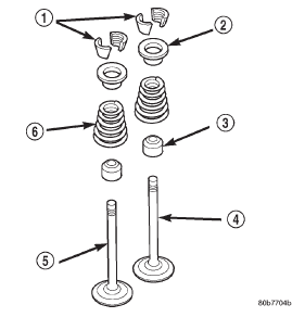
Fig. 9 Valve and Keeper Configuration 4.0L Engine
2 - RETAINER
3 - VALVE STEM OIL SEAL
4 - INTAKE VALVE
5 - EXHAUST VALVE
6 - VALVE SPRINGCylinder head cover
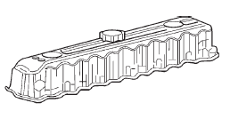
Fig. 10 Cylinder Head CoverHydraulic tappet
Valve stem seal
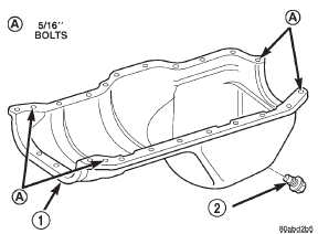
2 - OIL PAN DRAIN PLUG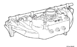
Fig. 12 Intake Manifold 4.0L EngineExhaust manifold
Other materials:
Oil pump and reaction shaft support
DISASSEMBLY
(1) Remove seal ring from housing and reaction
shaft support (Fig. 171).
Fig. 171 Removing Pump Seal Ring
1 - PUMP HOUSING SEAL RING
(2) Mark pump housing and support assembly for
alignment reference.
(3) Remove bolts attaching pump body to support
(Fig. 172).
Fig. 172 ...


