Jeep Cherokee (XJ): Oil pump and reaction shaft support
DISASSEMBLY
(1) Remove seal ring from housing and reaction shaft support (Fig. 171).
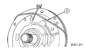
Fig. 171 Removing Pump Seal Ring
1 - PUMP HOUSING SEAL RING
(2) Mark pump housing and support assembly for alignment reference.
(3) Remove bolts attaching pump body to support (Fig. 172).
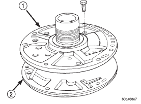
Fig. 172 Pump Support Bolts
1 - REACTION SHAFT SUPPORT
2 - PUMP
(4) Separate support from pump housing (Fig.
173).
(5) Remove inner and outer gears from reaction shaft support (Fig. 174).
(6) If pump seal was not removed during transmission disassembly, remove seal with punch and hammer.
(7) Remove front clutch thrust washer from support hub (Fig. 175).
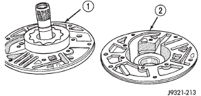
Fig. 173 Separating Pump Housing From Reaction Shaft Support
1 - REACTION SHAFT SUPPORT
2 - PUMP HOUSING
1 - REACTION SHAFT SUPPORT
2 - INNER GEAR
3 - OUTER GEAR
1 - BUSHING
2 - REACTION SHAFT SUPPORT
3 - THRUST WASHER
4 - HUB
OIL PUMP BUSHING REPLACEMENT
(1) Remove pump bushing with Tool Handle C-4171 and Bushing Remover SP-3551 from Tool Set C-3887-J (Fig. 176).
(2) Install new pump bushing with Tool Handle C-4171 and Bushing Installer SP-5117 (Fig. 176).
Bushing should be flush with pump housing bore.
(3) Stake new pump bushing in two places with blunt punch (Fig. 177). Remove burrs from stake points with knife blade afterward.
REACTION SHAFT SUPPORT BUSHING REMOVAL
(1) Assemble Bushing Remover Tools SP-1191, 3633 and 5324 (Fig. 178). Do not clamp any part of reaction shaft or support in vise.
(2) Hold Cup Tool SP-3633 firmly against reaction shaft and thread remover SP-5324 into bushing as far as possible by hand. Then thread remover tool 3-4 additional turns into bushing with a wrench.
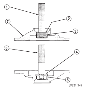
1 - SPECIAL TOOL C-4171
2 - SPECIAL TOOL SP-3551
3 - BUSHING
4 - SPECIAL TOOL SP-5117
5 - BUSHING
6 - SPECIAL TOOL C-4171
7 - PUMP HOUSING
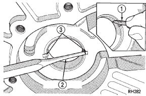
1 - NARROW BLADE
2 - BLUNT PUNCH
3 - TWO STAKES
(3) Turn remover tool hex nut down against remover cup to pull bushing from shaft. Clean all chips from shaft after bushing removal.
(4) Lightly grip old bushing in vise or with pliers and back remover tool out of bushing.
(5) Assemble Bushing Installer Tools C-4171 and SP-5325 (Fig. 178).
(6) Slide new bushing onto Installer Tool SP-5325.
(7) Position reaction shaft support upright on a clean smooth surface.
(8) Align bushing in bore. Then tap bushing into place until Bushing Installer SP-5325 bottoms.
(9) Clean reaction shaft support thoroughly after installing bushing.
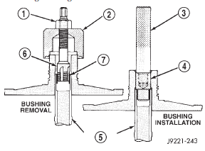
Fig. 178 Replacing Reaction Shaft Support Bushing
1 - SPECIAL TOOL SP-1191
2 - SPECIAL TOOL SP-3633
3 - SPECIAL TOOL C-4171
4 - SPECIAL TOOL SP-5325
5 - REACTION SHAFT
6 - SPECIAL TOOL SP-5324
7 - BUSHING
ASSEMBLY
(1) Lubricate gear bore in pump housing with transmission fluid.
(2) Lubricate pump gears with transmission fluid.
(3) Support pump housing on wood blocks (Fig.
179).
(4) Install outer gear in pump housing (Fig. 179).
Gear can be installed either way (it is not a one-way fit).
(5) Install pump inner gear (Fig. 180).
CAUTION: The pump inner gear is a one way fit.
The bore on one side of the gear inside diameter (I.
D.) is chamfered. Be sure the chamfered side faces forward (to front of pump).
(6) Install new thrust washer on hub of reaction shaft support. Lubricate washer with transmission fluid or petroleum jelly.
(7) If reaction shaft seal rings are being replaced, install new seal rings on support hub (Fig. 181).
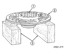
Fig. 179 Supporting Pump And Installing Outer Gear
1 - OUTER GEAR
2 - PUMP HOUSING
3 - WOOD BLOCKS
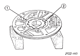
Fig. 180 Pump Inner Gear Installation
1 - OUTER GEAR
2 - INNER GEAR
Lubricate seal rings with transmission fluid or petroleum jelly after installation. Squeeze each ring until ring ends are securely hooked together.
CAUTION: The reaction shaft support seal rings will break if overspread, or twisted. If new rings are being installed, spread them only enough for installation.
Also be very sure the ring ends are securely hooked together after installation. Otherwise, the rings will either prevent pump installation, or break during installation.
(8) Install reaction shaft support on pump housing (Fig. 182).
(9) Align reaction support on pump housing. Use alignment marks made at disassembly. Or, rotate support until bolt holes in support and pump housing are all aligned (holes are offset for one-way fit).
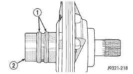
Fig. 181 Hub Seal Ring Position
1 - SEAL RINGS
2 - SUPPORT HUB
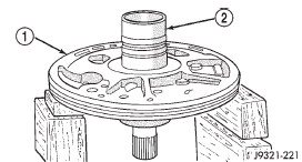
Fig. 182 Assembling Reaction Shaft Support And Pump Housing
1 - PUMP HOUSING
2 - REACTION SHAFT SUPPORT
(10) Install all bolts that attach support to pump housing. Then tighten bolts finger tight.
(11) Tighten support-to-pump bolts to required torque as follows: (a) Reverse pump assembly and install it in transmission case. Position pump so bolts are facing out and are accessible.
(b) Secure pump assembly in case with 2 or 3 bolts, or with pilot studs.
(c) Tighten support-to-pump bolts to 20 N·m (15 ft. lbs.).
(d) Remove pump assembly from transmission case.
(12) Install new oil seal in pump with Special Tool C-4193 and Tool Handle C-4171 (Fig. 183). Be sure seal lip faces inward.
(13) Install new seal ring around pump housing.
Be sure seal is properly seated in groove.
(14) Lubricate lip of pump oil seal and O-ring seal with transmission fluid.

Fig. 183 Pump Oil Seal Installation
1 - PUMP BODY
2 - PUMP SEAL
3 - SPECIAL TOOL C-4193
 Overrunning clutch/low-reverse
drum. Front servo piston. Rear servo piston
 Front clutch. Rear clutch. Planetary geartrain/output shaft
Other materials:
Vehicle identification number
The Vehicle Identification Number (VIN) is found on the
left front corner of the instrument panel. The VIN is visible
from outside of the vehicle through the windshield. The
VIN number also is stamped into the right front body, on
the right front seat cross member. With the seat in the rear
mos ...
