Jeep Cherokee (XJ): Description and operation
DESCRIPTION The 181 Front Beam-design Iron (FBI) axle consists
of a cast iron differential housing with axle
shaft tubes extending from either side. The tubes are
pressed into the differential housing and welded.
The integral type housing, hypoid gear design has
the centerline of the pinion set above the centerline
of the ring gear.
The axle has a fitting for a vent hose used to
relieve internal pressure caused by lubricant vaporization
and internal expansion.
The axles are equipped with semi-floating axle
shafts, meaning that loads are supported by the hub
bearings. The axle shafts are retained by nuts at the
hub bearings. The hub bearings are bolted to the
steering knuckle at the outboard end of the axle tube
yoke. The hub bearings are serviced as an assembly.
For vehicles with ABS brakes, the ABS wheel
speed sensors are attached to the knuckle assemblies.
The tone rings for the ABS system are pressed
onto the axle shaft. Do not damage ABS tone
wheel or the sensor when removing axle shafts.
The stamped steel cover provides a means for
inspection and servicing the differential.
The 181 FBI axle has the assembly part number
and gear ratio listed on a tag. The tag is attached to
the housing cover by a cover bolt. Build date identification
codes are stamped on the cover side of the
axle shaft tube.
The differential case is a one-piece design. The differential
pinion mate shaft is retained with a roll
pin. Differential bearing preload and ring gear backlash
is adjusted by the use of shims (select thickness).
The shims are located between the differential
bearing cones and case. Pinion bearing preload is set
and maintained by the use of shims (select thickness). OPERATION The axle receives power from the transfer case
through the front propeller shaft. The front propeller
shaft is connected to the pinion gear which rotates
the differential through the gear mesh with the ring
gear bolted to the differential case. The engine power
is transmitted to the axle shafts through the pinion
mate and side gears. The side gears are splined to
the axle shafts. DESCRIPTION The 186 Front Beam-design Iron (FBI) axle consists
of a cast iron differential housing with axle
shaft tubes extending from either side. The tubes are
pressed into the differential housing and welded.
The integral type housing, hypoid gear design has
the centerline of the pinion set below the centerline
of the ring gear.
The axle has a fitting for a vent hose used to
relieve internal pressure caused by lubricant vaporization
and internal expansion.
The axles are equipped with semi-floating axle
shafts, meaning that loads are supported by the hub
bearings. The axle shafts are retained by nuts at the
hub bearings. The hub bearings are bolted to the
steering knuckle at the outboard end of the axle tube
yoke. The hub bearings are serviced as an assembly.
For vehicles with ABS brakes, the ABS wheel
speed sensors are attached to the knuckle assemblies.
The tone rings for the ABS system are pressed
onto the axle shaft. Do not damage ABS tone
wheel or the sensor when removing axle shafts.
The stamped steel cover provides a means for
inspection and servicing the differential.
The 186 FBI axle has the assembly part number
and gear ratio listed on a tag. The tag is attached to
the housing cover by a cover bolt. Build date identification
codes are stamped on the cover side of the
axle shaft tube.
The differential case is a one-piece design. The differential
pinion mate shaft is retained with a roll
pin. Differential bearing preload and ring gear backlash
is adjusted by the use of shims (select thickness).
The shims are located between the differential
bearing cones and case. Pinion bearing preload is set
and maintained by the use of a collapsible spacer. OPERATION The axle receives power from the transfer case
through the front propeller shaft. The front propeller
shaft is connected to the pinion gear which rotates
the differential through the gear mesh with the ring
gear bolted to the differential case. The engine power
is transmitted to the axle shafts through the pinion
mate and side gears. The side gears are splined to
the axle shafts. DESCRIPTION A multi-purpose, hypoid gear lubricant which conforms
to the following specifications should be used.
Mopart Hypoid Gear Lubricant conforms to all of
these specifications. The 181 FBI axle lubricant capacity is 1.2 L (2.5
pts.). The 186 FBI axle lubricant capacity is 1.18 L
(2.5 pts.).
CAUTION: If axle is submerged in water, lubricant
must be replaced immediately to avoid possible
premature axle failure. DESCRIPTION The differential gear system divides the torque
between the axle shafts. It allows the axle shafts to
rotate at different speeds when turning corners.
Each differential side gear is splined to an axle
shaft. The pinion gears are mounted on a pinion
mate shaft and are free to rotate on the shaft. The
pinion gear is fitted in a bore in the differential case
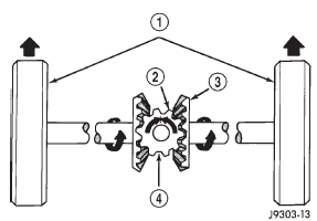
and is positioned at a right angle to the axle shafts. OPERATION In operation, power flow occurs as follows: During straight-ahead driving, the differential pinion
gears do not rotate on the pinion mate shaft. This
occurs because input torque applied to the gears is
divided and distributed equally between the two side
gears. As a result, the pinion gears revolve with the
pinion mate shaft but do not rotate around it (Fig. 1).
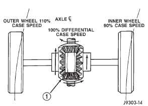
When turning corners, the outside wheel must
travel a greater distance than the inside wheel to
complete a turn. The difference must be compensated
for to prevent the tires from scuffing and skidding
through turns. To accomplish this, the differential
allows the axle shafts to turn at unequal speeds (Fig.
2). In this instance, the input torque applied to the
pinion gears is not divided equally. The pinion gears
now rotate around the pinion mate shaft in opposite
directions. This allows the side gear and axle shaft
attached to the outside wheel to rotate at a faster
speed.
1 - IN STRAIGHT AHEAD DRIVING EACH WHEEL ROTATES AT
100% OF CASE SPEED
1 - PINION GEARS ROTATE ON PINION SHAFT181 FBI axle
186 FBI axle
Lubricant
Standard differential

Fig. 1 Differential Operation-Straight Ahead Driving
2 - PINION GEAR
3 - SIDE GEAR
4 - PINION GEARS ROTATE WITH CASE
Fig. 2 Differential Operation-On Turns
Other materials:
Transmission valve body components
DESCRIPTION
Transmission operating pressure is supplied to the
clutch and brake apply circuits through the transmission
valve body. The valve body consists of an upper
body, lower body, separator plate and upper and
lower gaskets (Fig. 14). The various spool valves,
sleeves, plugs and springs ...


