Jeep Cherokee (XJ): Transmission valve body components
DESCRIPTION
Transmission operating pressure is supplied to the clutch and brake apply circuits through the transmission valve body. The valve body consists of an upper body, lower body, separator plate and upper and lower gaskets (Fig. 14). The various spool valves, sleeves, plugs and springs are located within the two body sections.
The manual valve, 1-2 shift valve, primary regulator valve, accumulator control valve, check balls, and oil strainers are located in the lower body section (Fig. 15). The remaining control and shift valves plus check balls and one additional oil strainer are located in the upper body section (Fig. 16).
TRANSMISSION VALVE BODY SOLENOIDS
The solenoids are mounted on the valve body and operated by the TCM. The solenoids control operation of the converter clutch and shift valves in response to input signals from the module.
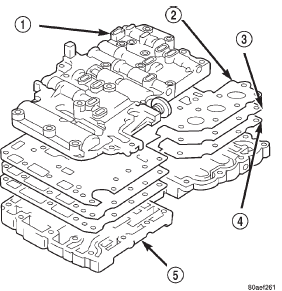
Fig. 14 Two-Section Transmission Valve Body
1 - UPPPER BODY
2 - UPPER GASKET
3 - SEPARATOR PLATE
4 - LOWER GASKET
5 - LOWER BODY
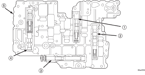
Fig. 15 Upper Body Components
1 - ACCUMULATOR CONTROL VALVE
2 - 1-2 SHIFT VALVE
3 - MANUAL VALVE
4 - PRIMARY REGULATOR VALVE
5 - LOWER BODY
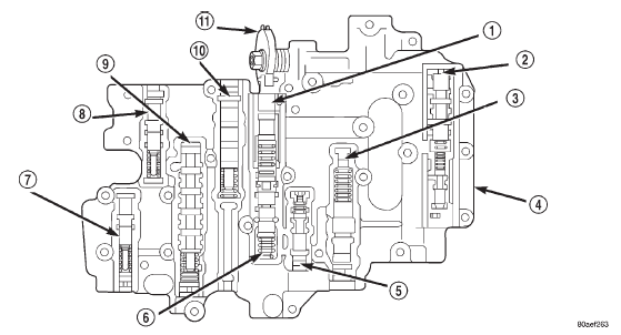
Fig. 16 Lower Body Components
1 - DOWNSHIFT PLUG
2 - LOCK-UP RELAY VALVE
3 - SECONDARY REGULATOR VALVE
4 - UPPER BODY
5 - CUT-BACK VALVE
6 - THROTTLE VALVE
7 - LOW COAST MODULATOR VALVE
8 - SECONDARY COAST MODULATOR VALVE
9 - 2-3 SHIFT VALVE
10 - 3-4 SHIFT VALVE
11 - THROTTLE CAM
OPERATION
MANUAL VALVE
The manual valve is operated by the gearshift linkage.
The valve diverts fluid to the apply circuits according to shift lever position (Fig. 17).
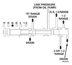
Fig. 17 Manual Valve
PRIMARY REGULATOR VALVE
The primary regulator valve (Fig. 18) modulates line pressure to the clutches and brakes according to engine load. The valve is actuated by throttle valve pressure.
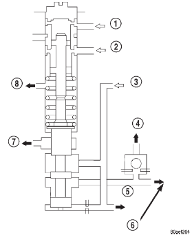
Fig. 18 Primary Regulator Valve
1 - THROTTLE PRESSURE
2 - LINE PRESSURE (FROM MANUAL VALVE "R" RANGE)
3 - LINE PRESSURE (FROM PUMP)
4 - CONVERTER PRESSURE TO CONVERTER CLUTCH RELAY
VALVE
5 - LINE PRESSURE
6 - CONVERTER PRESSURE (TO SECONDARY REGULATOR
VALVE)
7 - DRAIN
8 - DRAIN
During high load operation, the valve increases line pressure to maintain positive clutch and brake engagement. At light load, the valve decreases line pressure just enough to maintain smooth engagement.
THROTTLE VALVE AND DOWNSHIFT PLUG
The throttle valve and downshift plug (Fig. 19) control throttle pressure to the primary regulator valve.
The downshift plug and throttle valve are operated by the throttle valve cam and throttle cable in response to engine throttle position. Throttle valve pressure is also modulated by the cut-back valve in second, third and fourth gear ranges.
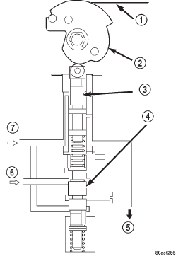
Fig. 19 Throttle Valve And Downshift Plug
1 - LINE PRESSURE CABLE
2 - THROTTLE VALVE CAM
3 - DOWNSHIFT PLUG
4 - THROTTLE VALVE
5 - THROTTLE PRESSURE (TO PRIMARY REGULATOR VALVE)
6 - LINE PRESSURE
7 - CUT-BACK PRESSURE (FROM CUT-BACK VALVE)
CUT-BACK VALVE
The cut-back valve (Fig. 20) helps prevent excessive pump pressure buildup in second, third and fourth gear. The valve is actuated by throttle pressure and by line pressure from the second brake. The valve also helps regulate line pressure by controlling the amount of cut-back pressure to the throttle valve.
SECONDARY REGULATOR VALVE
The secondary regulator valve (Fig. 21) regulates converter clutch and transmission lubrication pressure.
When primary regulator valve pressure exceeds requirements for clutch engagement or transmission lubrication, the secondary regulator valve is moved upward exposing the drain port. Excess pressure then bleeds off as needed. As pressure drops, spring
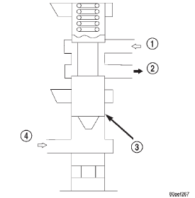
Fig. 20 Cut-Back Valve
1 - THROTTLE PRESSURE
2 - CUT-BACK PRESSURE TO THROTTLE VALVE
3 - CUT-BACK VALVE
4 - SECOND BRAKE LINE PRESSURE
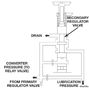
Fig. 21 Secondary Regulator Valve
CONVERTER CLUTCH RELAY VALVE
The converter clutch relay valve (Fig. 22) controls fluid flow to the converter clutch. The valve is operated by line pressure from the 1-2 shift valve and is controlled by solenoid valve number three.
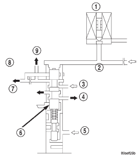
Fig. 22 Converter Clutch Relay Valve
1 - SOLENOID VALVE NO. 3
2 - LINE PRESSURE (FROM 1-2 SHIFT VALVE)
3 - CONVERTER PRESSURE
4 - DRAIN
5 - LINE PRESSURE (FROM PUMP)
6 - CONVERTER CLUTCH RELAY VALVE
7 - TO CONVERTER CLUTCH (DISENGAGED)
8 - TO OIL COOLER
9 - TO CONVERTER CLUTCH (ENGAGED)
1-2 SHIFT VALVE
The 1-2 shift valve (Fig. 23) controls the 1-2 upshifts and downshifts. The valve is operated by the No. 2 valve body solenoid and line pressure from the manual valve, second coast modulator valve and the 2-3 shift valve.
When the transmission control module deactivates the solenoid, line pressure at the top of the valve moves the valve down closing the second brake accumulator feed port. As the solenoid is activated and the drain port opens, spring force moves the valve up exposing the second brake feed port for the shift to second gear.
2-3 SHIFT VALVE
The 2-3 shift valve (Fig. 24) controls the 2-3 upshifts and downshifts. The valve is actuated by the No. 1 valve body solenoid and by line pressure from the manual valve and primary regulator valve.
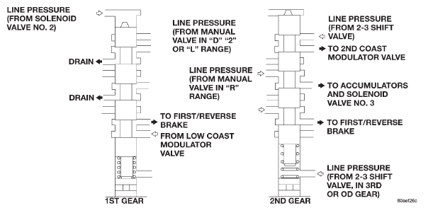
Fig. 23 1-2 Shift Valve
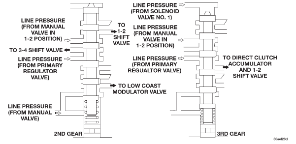
Fig. 24 2-3 Shift Valve
When the TCM activates solenoid No. 1, line pressure at the top of the 2-3 valve is released through the solenoid drain port. Spring tension moves the valve up to hold the valve in second gear position. As the solenoid is deactivated, line pressure then moves the valve down exposing the direct clutch feed port for the shift to third gear.
3-4 SHIFT VALVE
The 3-4 shift valve (Fig. 25) is operated by the No.
2 solenoid and by line pressure from the manual valve, 2-3 valve and primary regulator valve.
Energizing the No. 2 solenoid causes line pressure at the top of the 3-4 valve to be released through the solenoid valve drain port. Spring tension moves the valve up exposing the overdrive clutch accumulator feed port to apply the clutch.
De-energizing the solenoid causes the drain port to close. Line pressure then moves the valve down exposing the overdrive brake accumulator feed port for the shift to fourth gear.
In the 1-2 or 3 gearshift lever positions, line pressure from the 2-3 shift valve is applied to the lower end of the 3-4 valve. This holds the valve upward, closing off the overdrive brake feed port preventing a shift into fourth gear.
SECOND COAST MODULATOR VALVE
The second coast modulator valve (Fig. 26) momentarily reduces line pressure from the 1-2 shift valve.
This cushions application of the second coast brake.
The valve is operative when the shift lever and manual valve are in the 3 position.
LOW COAST MODULATOR VALVE
The low coast modulator valve (Fig. 27) momentarily reduces line pressure from the 2-3 shift valve; this action cushions application of the first/reverse brake. The modulator valve operates when the shift lever and manual valve are in the 1-2 position.
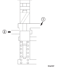
Fig. 26 Second Coast Modulator Valve
1 - TO OVER DRIVE BRAKE ACCUMULATOR
2 - LINE PRESSURE (FROM PRIMARY REGULATOR VALVE)
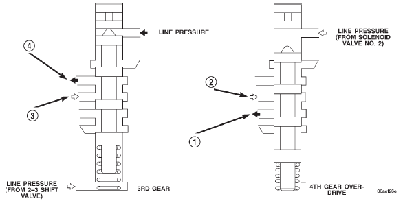
Fig. 25 3-4 Shift Valve
1 - LINE PRESSURE (FROM 1-2 SHIFT VALVE)
2 - LOW COAST MODULATOR PRESSURE SECOND COAST
BRAKE
3 - LINE PRESSURE (FROM PRIMARY REGULATOR VALVE)
4 - TO OVERDRIVE CLUTCH ACCUMULATOR

Fig. 27 Low Coast Modulator Valve
1 - LINE PRESSURE (FROM 2-3 SHIFT VALVE)
2 - LOW COAST MODULATOR PRESSURE TO FIRST/REVERSE
BRAKE
ACCUMULATOR CONTROL VALVE
The accumulator control valve (Fig. 28) cushions the transmission clutch and brake applications. This is achieved by reducing back pressure to the accumulators when throttle opening is small. The valve is operated by line and throttle pressure.
ACCUMULATORS
Four accumulators are used to cushion clutch and brake application. The accumulators (Fig. 29), consist of spring loaded pistons. The pistons dampen the initial surge of apply pressure to provide smooth engagement during shifts.
Control pressure from the accumulator control valve is continuously applied to the back pressure side of the accumulator pistons. This pressure plus spring tension holds the pistons down. As line pressure from the shift valves enters the opposite end of the piston bore, control pressure and spring tension momentarily delay application of full line pressure to cushion engagement. The accumulators are all located in the transmission case (Fig. 29).
TRANSMISSION VALVE BODY SOLENOIDS
Three solenoids are used (Fig. 30). The No. 1 and 2 solenoids control shift valve operation by applying or releasing line pressure. The signal to apply or release pressure is provided by the transmission control module.

Fig. 28 Accumulator Control Valve
1- ACCUMULATOR CONTROL PRESSURE (TO
ACCUMULATORS)
2 - THROTTLE PRESSURE
3 - LINE PRESSURE (FROM PUMP)
The No. 3 solenoid controls operation of the torque converter clutch. The solenoid operates in response to signals from the transmission control module.
When the No. 1 and 2 solenoids are activated, the solenoid plunger is moved off its seat opening the drain port to release line pressure. When either solenoid is deactivated, the plunger closes the drain port.
The No. 3 solenoid operates in reverse. When the solenoid is deactivated, the solenoid plunger is moved off its seat opening the drain port to release line pressure. When the solenoid is activated, the plunger closes the drain port.
 Fluid. Torque converter. Oil pump
Other materials:
Rear door waterdam. Rear door. Rear door restraint
Rear door waterdam
REMOVAL
(1) Remove door trim panel.
(2) Peel the waterdam from the door.
(3) Route the latch rods and wire harnesses
through the waterdam.
(4) Separate the waterdam from the door inner
panel.
INSTALLATION
(1) Route the latch rods and wire harnesses
through the water ...

