Jeep Cherokee (XJ): Description and operation
DESCRIPTION The 8 1/4 inch axle housings consist of a cast iron
center section with axle tubes extending from either
side. The tubes are pressed into and welded to the
differential housing to form a one-piece axle housing
(Fig. 1).
The axles have a vent hose to relieve internal pressure
caused by lubricant vaporization and internal
expansion.
The axles are equipped with semi-floating axle
shafts, meaning vehicle loads are supported by the
axle shaft and bearings. The axle shafts are retained
by C-locks in the differential side gears.
The removable, stamped steel cover provides a
means for inspection and service without removing
the complete axle from the vehicle.
The 8 1/4 axle have a date tag and a gear ratio tag.
The tags are attached to the differential housing by a
cover bolt.
The differential case is a one-piece design. The differential
pinion mate shaft is retained with a
threaded pin. Differential bearing preload and ring
gear backlash are set and maintained by threaded
adjusters at the outside of the differential housing.
Pinion bearing preload is set and maintained by the
use of a collapsible spacer.
Axles equipped with a Trac-Loky differential are
optional. A Trac-Lok differential has a one-piece differential
case, and the same internal components as
a standard differential, plus two clutch disc packs. AXLE IDENTIFICATION The axle differential cover can be used for identification
of the axle (Fig. 2). A tag is also attached to
the cover. OPERATION The axle receives power from the transmission/
transfer case through the rear propeller shaft. The
rear propeller shaft is connected to the pinion gear
which rotates the differential through the gear mesh
with the ring gear bolted to the differential case. The
engine power is transmitted to the axle shafts
through the pinion mate and side gears. The side
gears are splined to the axle shafts.
1 - DIFFERENTIAL COVER DESCRIPTION Multi-purpose, hypoid gear lubricant should be
used for rear axles with a standard differential. The
lubricant should have a MIL-L-2105C and API GL 5
quality specifications.
Trac-Lok differentials require the addition of 4 oz.
of friction modifier to the axle lubricant after service.
The 8 1/4 axle lubricant capacity is 2.08 L (4.4 pts.)
total, including the friction modifier, if necessary.
CAUTION: If the rear axle is submerged in water,
the lubricant must be replaced immediately. Avoid
the possibility of premature axle failure resulting
from water contamination of the lubricant. DESCRIPTION The differential gear system divides the torque
between the axle shafts. It allows the axle shafts to
rotate at different speeds when turning corners.
Each differential side gear is splined to an axle
shaft. The pinion gears are mounted on a pinion
mate shaft and are free to rotate on the shaft. The
pinion gear is fitted in a bore in the differential case
and is positioned at a right angle to the axle shafts. OPERATION In operation, power flow occurs as follows: During straight-ahead driving, the differential pinion
gears do not rotate on the pinion mate shaft. This
occurs because input torque applied to the gears is
divided and distributed equally between the two side
gears. As a result, the pinion gears revolve with the
pinion mate shaft but do not rotate around it (Fig. 3).
1 - IN STRAIGHT AHEAD DRIVING EACH WHEEL ROTATES AT
100% OF CASE SPEED When turning corners, the outside wheel must
travel a greater distance than the inside wheel to
complete a turn. The difference must be compensated
for to prevent the tires from scuffing and skidding
through turns. To accomplish this, the differential
allows the axle shafts to turn at unequal speeds (Fig.
4). In this instance, the input torque applied to the
pinion gears is not divided equally. The pinion gears
now rotate around the pinion mate shaft in opposite
directions. This allows the side gear and axle shaft
attached to the outside wheel to rotate at a faster
speed.
1 - PINION GEARS ROTATE ON PINION SHAFT DESCRIPTION In a standard differential, if one wheel spins, the
opposite wheel will generate only as much torque as
the spinning wheel.
In the Trac-loky differential, part of the ring gear
torque is transmitted through clutch packs which
contain multiple discs. The clutches will have radial
grooves on the plates, and concentric grooves on the
discs or bonded fiber material that is smooth in
appearance. OPERATION In operation, the Trac-loky clutches are engaged
by two concurrent forces. The first being the preload
force exerted through Belleville spring washers
within the clutch packs. The second is the separating
forces generated by the side gears as torque is
applied through the ring gear (Fig. 5).
1 - CASE The Trac-loky design provides the differential
action needed for turning corners and for driving
straight ahead during periods of unequal traction.
When one wheel looses traction, the clutch packs
transfer additional torque to the wheel having the
most traction. Trac-loky differentials resist wheel
spin on bumpy roads and provide more pulling power
when one wheel looses traction. Pulling power is provided
continuously until both wheels loose traction. If
both wheels slip due to unequal traction, Trac-loky
operation is normal. In extreme cases of differences
of traction, the wheel with the least traction may
spin.8 1/4 Axle
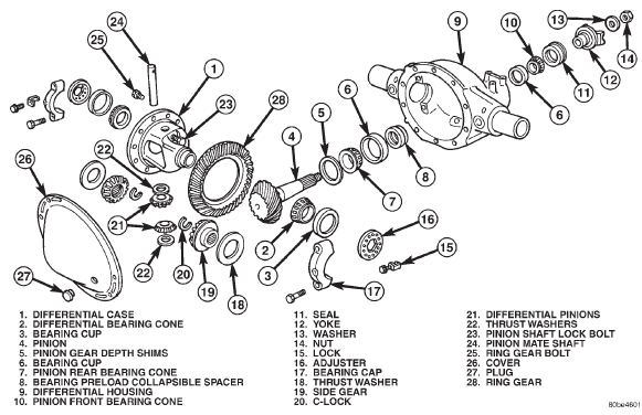
Fig. 1 8 1/4 Axle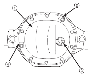
Fig. 2 Differential Cover 8 1/4 Inch Axle
2 - IDENTIFICATION TAG
3 - PUSH-IN FILL PLUG
4 - DATE TAGLubricant
Standard differential
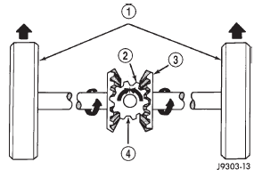
Fig. 3 Differential Operation-Straight Ahead Driving
2 - PINION GEAR
3 - SIDE GEAR
4 - PINION GEARS ROTATE WITH CASE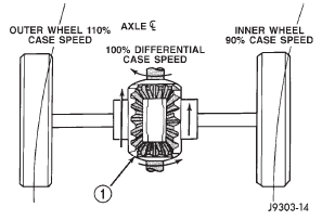
Fig. 4 Differential Operation-On TurnsTrac-lok differential
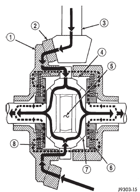
Fig. 5 Trac-lokY Limited Slip Differential Operation
2 - RING GEAR
3 - DRIVE PINION
4 - PINION GEAR
5 - MATE SHAFT
6 - CLUTCH PACK
7 - SIDE GEAR
8 - CLUTCH PACK


Other materials:
Rearview mirror support bracket. Sunvisors. Headliner
Rearview mirror support bracket
INSTALLATION
(1) Mark the position for the mirror bracket on the
outside of the windshield glass with a wax pencil.
(2) Clean the bracket contact area on the glass.
Use a mild powdered cleanser on a cloth saturated
with isopropyl (rubbing) alcohol. Finally, c ...