Jeep Cherokee (XJ): Diagnosis and testing
On models without the Remote Keyless Entry
(RKE) option, proceed directly to the Door Module
diagnosis. As a preliminary diagnosis for models with
the RKE system, note the power lock system and
illuminated entry system operation while you actuate
both the Lock and Unlock functions with the power
lock switches and the RKE transmitter. Then, proceed
as follows: If the power lock system is inoperative with either
front door power lock switch, test the Passenger Door
Module (PDM). If the power lock system is inoperative
with only the driver side front door power lock
switch, test the Driver Door Module (DDM). For circuit
descriptions and diagrams, refer to 8W-61 -
Power Door Locks in Group 8W - Wiring Diagrams. The only function of the Driver Door Module
(DDM) in the power lock system is to provide a Lock
or Unlock signal to the power lock system control circuitry
contained within the Passenger Door Module
(PDM). The DDM signals the PDM by providing a
hard-wired ground path through the DDM ground
circuit and the driver side power lock switch contacts
to the lock request or unlock request terminals of the
PDM. The DDM power lock switch function can be
tested as follows:
(1) Disconnect and isolate the battery negative
cable. Remove the driver side front door trim panel
and unplug the 12-way DDM wire harness connector
(C-2) from the DDM. Check for continuity between
the ground circuit cavity of the 12-way DDM wire
harness connector and a good ground. There should
be continuity. If OK, go to Step 2. If not OK, repair
the open circuit to ground as required.
(2) If the problem being diagnosed is inoperative
power lock switch illumination, proceed as follows. If
the problem is not power lock switch illumination, go
to Step 4. Connect the battery negative cable. Turn
the ignition switch to the Accessory or On positions.
Check for battery voltage at both sides of the power
window circuit breaker in the junction block. If OK,
go to Step 3. If not OK, replace the faulty circuit
breaker.
(3) With the ignition switch still in the On or
Accessory position, check for battery voltage at the
fused ignition switch output circuit cavity of the
12-way DDM wire harness connector. If OK, replace
the faulty DDM. If not OK, repair the open circuit to
the junction block as required.
(4) Test the power lock switch continuity through
the DDM 12-way wire harness connector receptacle.
See the DDM Power Lock Switch Continuity chart
(Fig. 1) to determine if the continuity is correct in
both the Lock and Unlock switch positions. If OK,
repair the lock request circuit and/or the unlock request circuit between the
DDM and the PDM as
required. If not OK, replace the faulty DDM.
PASSENGER DOOR MODULE The Passenger Door Module (PDM) contains the
passenger side front door power lock switch and the
power lock system control circuitry. In its role as a
power lock switch, it provides the power lock system
control circuitry with a ground path through the
PDM ground circuit and the driver side power lock
switch contacts to indicate a lock request or unlock
request.
In its role as the power lock control module, the
PDM receives inputs from the battery, the ignition
switch, the DDM, the driver door ajar switch, the
key-in ignition switch, and the headlamp switch. It
also receives a hard-wired input from the RKE
receiver, if the vehicle is so equipped. In response to
these inputs, the PDM sends the proper outputs to
control the power lock motors through its integral
power lock and unlock relays. The PDM power lock
system functions can be tested as outlined below. If
the power lock system operates, but the RKE system
lock and/or unlock functions are inoperative, see the
diagnosis for the Remote Keyless Entry Transmitter
in this group.
(1) Check the fuse in the junction block. If OK, go
to Step 2. If not OK, repair the shorted circuit or
component as required and replace the faulty fuse.
(2) Disconnect and isolate the battery negative
cable. Remove the passenger side front door trim
panel and unplug the 8-way PDM wire harness connector
(C-1) from the PDM. Check for continuity
between the ground circuit cavity of the 8-way PDM
wire harness connector and a good ground. There
should be continuity. If OK, go to Step 3. If not OK,
repair the open circuit to ground as required.
(3) If the problem being diagnosed is inoperative
power lock switch illumination, proceed as follows. If
the problem is not power lock switch illumination, go
to Step 5. Connect the battery negative cable. Turn
the ignition switch to the Accessory or On positions.
Check for battery voltage at both sides of the power
window circuit breaker in the junction block. If OK,
go to Step 4. If not OK, replace the faulty circuit
breaker.
(4) With the ignition switch still in the Accessory
or On positions, check for battery voltage at the
fused ignition switch output circuit cavity of the
8-way PDM wire harness connector. If OK, replace
the faulty PDM. If not OK, repair the open circuit to
the junction block as required.
(5) If the problem being diagnosed is an inoperative
door lock inhibit feature or a power lock system
that responds to an Unlock command, but not a Lock
command, proceed as follows. Otherwise, go to Step
7. With the driver side front door closed, check for
continuity between the door ajar/key-in circuit cavity
of the 8-way PDM wire harness connector and a good
ground. There should be no continuity. If OK, go to
Step 6. If not OK, repair the shorted door ajar and/or
key-in ignition circuits as required. Refer to Group
8U - Chime/Buzzer Warning Systems for more information.
(6) Open the driver side front door with the key in
the ignition switch or with the headlamp switch in
the On position. Check for continuity between the
door ajar/key-in circuit cavity of the 8-way PDM wire
harness connector and a good ground. There should
be continuity. If OK, go to Step 8. If not OK, repair
the open door ajar and/or key-in ignition circuits as
required. Refer to Group 8U - Chime/Buzzer Warning
Systems for more information.
(7) Connect the battery negative cable. Check for
battery voltage at the fused B(+) circuit cavity of the
8-way PDM wire harness connector. If OK, go to Step
8. If not OK, repair the open circuit to the fuse in the
junction block as required.
(8) Test the PDM power lock switch continuity
through the two PDM wire harness connector receptacles.
See the PDM Power Lock Switch Continuity
chart (Fig. 2) to determine if the continuity is correct
in both the Lock and Unlock switch positions. If OK,
see the diagnosis for Power Lock Motors in this
group. If not OK, replace the faulty PDM. Before you proceed with this diagnosis, confirm
proper power door lock switch operation. See Door
Module in this group for the diagnostic procedures.
Remember, the Passenger Door Module (PDM) circuitry
controls the output to each of the power lock
motors. For circuit descriptions and diagrams, refer
to 8W-61 - Power Door Locks in Group 8W - Wiring
Diagrams.
(1) Check each power lock motor for correct operation
while moving the power lock switch to both the
Lock and Unlock positions. If all of the power lock
motors are inoperative, go to Step 2. If one power
lock motor is inoperative, go to Step 3.
(2) If all of the power lock motors are inoperative,
the problem may be caused by one shorted motor.
Unplugging a shorted power lock motor from the
power lock circuit will allow the good power lock
motor to operate. Unplug each power lock motor wire
harness connector, one at a time, and recheck both
the lock and unlock functions by operating the power
lock switch. If all of the power lock motors are still
inoperative after the above test, check for a short or
open circuit between the power lock motors and the
PDM. If unplugging one power lock motor causes the
other motors to become functional, go to Step 3 to
test the unplugged motor.
(3) Once it is determined which power lock motor
is inoperative, that motor can be tested as follows.
Unplug the wire harness connector at the inoperative
power lock motor. Apply 12 volts to the motor terminals
to check its operation in one direction. Reverse
the polarity to check the operation in the other direction.
If OK, repair the short or open circuits between
the power lock motor and the PDM as required. If
not OK, replace the faulty power lock motor. REMOTE KEYLESS ENTRY TRANSMITTER (1) Replace the Remote Keyless Entry (RKE)
transmitter batteries. See Remote Keyless Entry
Transmitter Battery Replacement in this group for
the procedures. Test each of the transmitter functions.
If OK, discard the faulty batteries. If not OK,
go to Step 2.
(2) Perform the Remote Keyless Entry Transmitter
Programming procedure with the suspect transmitter
and another known good transmitter. Use a DRB
scan tool, as described in the proper Diagnostic Procedures
manual.
(3) Test the RKE system operation with both
transmitters. If both transmitters fail to operate the
power lock system, see the diagnosis for the Remote
Keyless Entry Receiver in this group. If the known
good transmitter operates the power locks and the
suspect transmitter does not, replace the faulty
transmitter.
NOTE: Be certain to perform the Remote Keyless
Entry Transmitter Programming procedure again
following this test. This procedure will erase the
access code of the test transmitter from the RKE
receiver. If the problem being diagnosed is an inoperative
Remote Keyless Entry (RKE) horn chirp feature, be
certain that the horn chirp feature has not been disabled.
See Remote Keyless Entry Receiver Programming
in this group for the procedures. Also be certain
that the vehicle horn system is operational. Refer to
Group 8G - Horn Systems for more information.
If the problem being diagnosed is an inoperative
RKE illuminated entry system, be certain that the
interior courtesy lamp system is operational. Refer to
Group 8L - Lamps for more information.
Before you proceed with diagnosis of the RKE
receiver, see the diagnosis for Remote Keyless Entry
Transmitter in this group. For circuit descriptions
and diagrams, refer to 8W-61 - Power Door Locks in
Group 8W - Wiring Diagrams.
(1) Check the fuses in the Power Distribution Center
(PDC) and the junction block. If OK, go to Step 2. If not OK, repair the shorted circuit or component as
required and replace the faulty fuse.
(2) Disconnect and isolate the battery negative
cable. Remove the Remote Keyless Entry (RKE)
receiver from the headliner. Unplug the wire harness
connector from the RKE receiver.
(3) Check the wire harness connector and the
receptacle in the RKE receiver for loose, corroded, or
damaged terminals and pins. If OK, go to Step 4. If
not OK, repair as required.
(4) Check for continuity between each of the two
ground circuit cavities of the RKE receiver wire harness
connector and a good ground. In each case,
there should be continuity. If OK, go to Step 5. If not
OK, repair the circuit to ground as required.
(5) Connect the battery negative cable. Check for
battery voltage at each of the two fused B(+) circuit
cavities of the RKE receiver wire harness connector.
If OK, go to Step 6. If not OK, repair the open circuit
to the PDC or the junction block as required.
(6) If the problem being diagnosed involves only
the RKE horn chirp feature, go to Step 10. If the
problem being diagnosed involves only the RKE illuminated
entry feature, go to Step 9. If the problem
being diagnosed involves only the RKE power lock
feature, go to Step 7.
(7) Disconnect and isolate the battery negative
cable. Unplug the 8-way Passenger Door Module
(PDM) wire harness connector. Check for continuity
between the lock request circuit cavity of the RKE
receiver wire harness connector and a good ground.
Repeat the test between the unlock request circuit
cavity of the RKE receiver wire harness connector
and a good ground. In each case, there should be no
continuity. If OK, go to Step 8. If not OK, repair the
shorted circuit as required.
(8) Check for continuity between the lock request
circuit cavities of the RKE receiver wire harness connector
and the 8-way PDM wire harness connector.
Repeat the test between the unlock request circuit
cavities of the RKE receiver wire harness connector
and the 8-way PDM wire harness connector. In each
case, there should be continuity. If OK, replace the
faulty RKE receiver. If not OK, repair the open circuit
as required.
(9) Check for continuity between the door ajar circuit
cavity of the RKE receiver wire harness connector
and a good ground with the driver door closed.
There should be no continuity until the driver door is
opened. If OK, replace the faulty RKE receiver. If not
OK, repair the circuit or replace the faulty driver
door ajar switch as required.
(10) Unplug the horn relay from the junction
block. Check for continuity between the horn relay
output circuit cavity of the RKE receiver wire harness
connector and a good ground. There should be
no continuity. If OK, go to Step 11. If not OK, repair
the short circuit to the horn relay as required.
(11) Check for continuity between the horn relay
output circuit cavity of the RKE receiver wire harness
connector and the junction block cavity for the
horn relay coil ground terminal (85). There should be
continuity. If OK, replace the faulty RKE receiver. If
not OK, repair the open circuit to the junction block
as required.Power lock system and remote
keyless entry system
Door module
Power lock motor
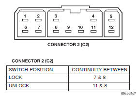
Fig. 1 DDM Power Lock Switch ContinuityRemote keyless entry transmitter
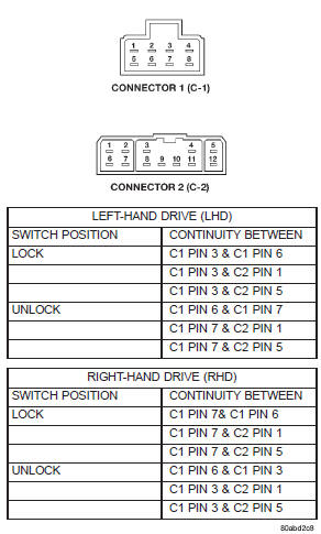
Fig. 2 PDM Power Lock Switch ContinuityRemote keyless entry receiver


Other materials:
Diagnosis and testing
Charging system
The following procedures may be used to diagnose
the charging system if:
the generator lamp (if equipped) is illuminated
with the engine running
the voltmeter (if equipped) does not register
properly
an undercharged or overcharged battery condition
oc ...