Jeep Cherokee (XJ): Dual function high pressure switch (4.0 L). Evaporator coil. Fixed orifice tube
DESCRIPTION The Dual Function High Pressure Switch controls
both A/C clutch engagement/disengagement, and electric
cooling fan operations. The switch is located on
the discharge line near the compressor. The switch is
screwed onto a fitting that contains a Schrader-type
valve, which allows the switch to be serviced without
discharging the refrigerant system. The discharge
line fitting is equipped with an O-ring to seal the
switch connection. OPERATION The dual function switch is connected in series
electrically with the low pressure cycling clutch
switch between ground and the Powertrain Control
Module (PCM). The switch contacts open and close
causing the PCM to turn the compressor clutch on
and off. This prevents compressor operation when the
discharge line pressure approaches high levels, and
also reduces electrical surging from compressor
clutch engagement.
The dual function switch controls the electric cooling
fan operation by monitoring refrigerant line pressures.
When the discharge line pressure rises above
1900 to 2200 kPa (280 to 320 psi) the fan will turn
on. The cooling fan will turn off when the discharge
line pressure drops to 1600 kPa (235 psi).
The dual function switch controls the A/C clutch
operation by disengaging the clutch when the discharge
line pressure rises above 3100 to 3375 kPa
(450 to 490 psi). The switch contacts will close and
allow A/C clutch engagement when the discharge line
pressure drops to 1860 to 2275 kPa (270 to 330 psi).
The Dual Function High Pressure Switch is a factory-
calibrated unit. The switch cannot be adjusted
or repaired and, if faulty or damaged, it must be
replaced. DESCRIPTION The evaporator coil is located in the heater-A/C
housing, under the instrument panel. The evaporator
coil is positioned in the heater-A/C housing so that all air that enters the
housing must pass over the
fins of the evaporator before it is distributed through
the system ducts and outlets. However, air passing
over the evaporator coil fins will only be conditioned
when the compressor is engaged and circulating
refrigerant through the evaporator coil tubes. OPERATION Refrigerant enters the evaporator from the fixed
orifice tube as a low-temperature, low-pressure liquid.
As air flows over the fins of the evaporator, the
humidity in the air condenses on the fins, and the
heat from the air is absorbed by the refrigerant. Heat
absorption causes the refrigerant to boil and vaporize.
The refrigerant becomes a low-pressure gas when
it leaves the evaporator.
The evaporator coil cannot be repaired and, if
faulty or damaged, it must be replaced. DESCRIPTION The fixed orifice tube is installed in the liquid line
(left-hand drive) or liquid line jumper (right-hand
drive) between the outlet of the condenser and the
inlet of the evaporator. The fixed orifice tube is
located in the end of the liquid line or liquid line
jumper that is closest to the condenser outlet tube.
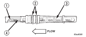
The inlet end of the fixed orifice tube has a nylon
mesh filter screen, which filters the refrigerant and
helps to reduce the potential for blockage of the
metering orifice by refrigerant system contaminants
(Fig. 3). The outlet end of the tube has a nylon mesh
diffuser screen. The O-rings on the plastic body of
the fixed orifice tube seal the tube to the inside of
the liquid line and prevent the refrigerant from
bypassing the fixed metering orifice.
1 - DIFFUSER SCREEN OPERATION The fixed orifice tube is used to meter the flow of
liquid refrigerant into the evaporator coil. The highpressure
liquid refrigerant from the condenser
expands into a low-pressure liquid as it passes
through the metering orifice and diffuser screen of
the fixed orifice tube.
The fixed orifice tube cannot be repaired and, if
faulty or plugged, the liquid line and fixed orifice
tube unit or liquid line jumper and fixed orifice tube
unit must be replaced.Dual function high pressure switch
(4.0 L)
Evaporator coil
Fixed orifice tube

Fig. 3 Fixed Orifice Tube - Typical
2 - "O" RINGS
3 - INLET FILTER SCREEN
4 - ORIFICE
 Compressor clutch. Compressor clutch relay. Condenser
 Heater and air conditioner. Heater and air conditioner control. Heater core
Other materials:
Service engine assembly (short
block). Hydrostatic lock. Engine oil service
Service engine assembly (short
block)
A service replacement engine assembly (short
block) may be installed whenever the original cylinder
block is defective or damaged beyond repair. It
consists of the cylinder block, crankshaft, piston and
rod assemblies. If needed, the camshaft must be procur ...
