Jeep Cherokee (XJ): Front clutch. Rear clutch. Planetary geartrain/output shaft
DISASSEMBLY (1) Remove waved snap ring and remove pressure
plate, clutch plates and clutch discs (Fig. 184).
(2) Compress clutch piston spring with Compressor
Tool C-3575-A (Fig. 185). Be sure legs of tool are
seated squarely on spring retainer before compressing
spring.
(3) Remove retainer snap ring and remove compressor
tool.
(4) Remove spring retainer and clutch spring. Note
position of retainer on spring for assembly reference.
(5) Remove clutch piston from clutch retainer.
Remove piston by rotating it up and out of retainer.
(6) Remove seals from clutch piston and clutch
retainer hub. Discard both seals as they are not reusable.
ASSEMBLY
(1) Soak clutch discs in transmission fluid while
assembling other clutch parts.
(2) Install new seals on piston and in hub of
retainer. Be sure lip of each seal faces interior of
clutch retainer.
(3) Lubricate lips of piston and retainer seals with
liberal quantity of Mopart Door Ease, or Ru-Glyde.
Then lubricate retainer hub, bore and piston with
light coat of transmission fluid.
(4) Install clutch piston in retainer (Fig. 186). Use
twisting motion to seat piston in bottom of retainer. A
thin strip of plastic (about 0.020" thick), can be used
to guide seals into place if necessary.
CAUTION: Never push the clutch piston straight in.
This will fold the seals over causing leakage and
clutch slip. In addition, never use any type of metal
tool to help ease the piston seals into place. Metal
tools will cut, shave, or score the seals.
1 - RETAINER HUB SEAL (5) Position spring in clutch piston (Fig. 187).
(6) Position spring retainer on top of piston spring
(Fig. 188). Make sure retainer is properly
installed. Small raised tabs should be facing
upward. Semicircular lugs on underside of
retainer are for positioning retainer in spring.
(7) Compress piston spring and retainer with Compressor
Tool C-3575-A (Fig. 185). Then install new
snap ring to secure spring retainer and spring.
(8) Install clutch plates and discs (Fig. 184).
Install steel plate then disc until all plates and discs
are installed. The front clutch uses 4 clutch discs.
(9) Install pressure plate and waved snap ring
(Fig. 184).
(10) Using a suitable gauge bar and dial indicator,
measure clutch plate clearance (Fig. 189).
(a) Position gauge bar across the clutch drum
with the dial indicator pointer on the pressure
plate (Fig. 189).
(b) Using two small screw drivers, lift the pressure
plate and compress the waved snap-ring. This
will assure that the snap-ring is at the top of the
groove.
(c) Release the pressure plate and zero the dial
indicator.
(d) Lift the pressure plate until it contacts the
waved snap-ring and record the dial indicator reading.
Clearance should be 1.70 to 3.40 mm (0.067 to
0.134 in.). If clearance is incorrect, clutch discs,
plates pressure plates and snap ring may have to be
changed. DISASSEMBLY (1) Remove thrust washer from forward side of
clutch retainer.
(2) Remove input shaft front/rear seal rings.
(3) Remove selective clutch pack snap ring (Fig.
190).
1 - FRONT CLUTCH SPRING
1 - CLUTCH PISTON (4) Remove top pressure plate, clutch discs, steel
plates, bottom pressure plate and wave snap ring
and wave spring (Fig. 190).
(5) Remove clutch piston with rotating motion.
(6) Remove and discard piston seals.
(7) Remove input shaft snap-ring (Fig. 191). It
may be necessary to press the input shaft in slightly
to relieve tension on the snap-ring
(8) Press input shaft out of retainer with shop
press and suitable size press tool. Use a suitably sized press tool to support
the retainer as close to the
input shaft as possible.
1 - RETAINER
1 - SMALL TABS ON RETAINER FACE UPWARD
1 - DIAL INDICATOR ASSEMBLY (1) Soak clutch discs in transmission fluid while
assembling other clutch parts.
(2) Install new seal rings on clutch retainer hub
and input shaft if necessary (Fig. 192).
(a) Be sure clutch hub seal ring is fully seated in
groove and is not twisted.
(3) Lubricate splined end of input shaft and clutch
retainer with transmission fluid. Then press input
shaft into retainer. Use a suitably sized press tool to
support retainer as close to input shaft as possible.
(4) Install input shaft snap-ring (Fig. 191).
(5) Invert retainer and press input shaft in opposite
direction until snap-ring is seated.
(6) Install new seals on clutch piston. Be sure lip
of each seal faces interior of clutch retainer.
(7) Lubricate lip of piston seals with generous
quantity of Mopart Door Ease. Then lubricate
retainer hub and bore with light coat of transmission
fluid.
(8) Install clutch piston in retainer. Use twisting
motion to seat piston in bottom of retainer. A thin
strip of plastic (about 0.020" thick), can be used to
guide seals into place if necessary.
CAUTION: Never push the clutch piston straight in.
This will fold the seals over causing leakage and
clutch slip. In addition, never use any type of metal
tool to help ease the piston seals into place. Metal
tools will cut, shave, or score the seals.
1 - PISTON SPRING
1 - REAR CLUTCH RETAINER (9) Install piston spring in retainer and on top of
piston (Fig. 195). Concave side of spring faces downward
(toward piston).
(10) Install wave spring in retainer (Fig. 195). Be
sure spring is completely seated in retainer groove.
1 - REAR CLUTCH RETAINER HUB SEAL RING (11) Install bottom pressure plate (Fig. 190).
Ridged side of plate faces downward (toward piston)
and flat side toward clutch pack.
1 - PLASTIC REAR SEAL RING
1 - INPUT SHAFT
1 - REAR CLUTCH RETAINER (12) Install first clutch disc in retainer on top of
bottom pressure plate. Then install a clutch plate followed
by a clutch disc until entire clutch pack is
installed (4 discs and 3 plates are required) (Fig.
190).
(13) Install top pressure plate.
(14) Install selective snap ring. Be sure snap ring
is fully seated in retainer groove.
(15) Using a suitable gauge bar and dial indicator,
measure clutch pack clearance (Fig. 196).
(a) Position gauge bar across the clutch drum
with the dial indicator pointer on the pressure
plate (Fig. 196).
(b) Using two small screw drivers, lift the pressure
plate and release it.
(c) Zero the dial indicator.
(d) Lift the pressure plate until it contacts the
snap-ring and record the dial indicator reading.
Clearance should be 0.64 - 1.14 mm (0.025 - 0.045
in.). If clearance is incorrect, steel plates, discs, selective
snap ring and pressure plates may have to be
changed.
The selective snap ring thicknesses are: (16) Coat rear clutch thrust washer with petroleum
jelly and install washer over input shaft and
into clutch retainer (Fig. 197). Use enough petroleum
jelly to hold washer in place.
1 - DIAL INDICATOR 1 - REAR CLUTCH RETAINER DISASSEMBLY (1) Remove planetary snap ring (Fig. 198).
(2) Remove front annulus and planetary assembly
from driving shell (Fig. 198).
(3) Remove snap ring that retains front planetary
gear in annulus gear (Fig. 199).
(4) Remove tabbed thrust washer and tabbed
thrust plate from hub of front annulus (Fig. 200).
(5) Separate front annulus and planetary gears
(Fig. 200). (6) Remove front planetary gear front thrust
washer from annulus gear hub.
(7) Separate and remove driving shell, rear planetary
and rear annulus from output shaft (Fig. 201).
(8) Remove front planetary rear thrust washer
from driving shell.
(9) Remove tabbed thrust washers from rear planetary
gear.
(10) Remove lock ring that retains sun gear in
driving shell. Then remove sun gear, spacer and
thrust plates.
1 - DRIVING SHELL
1 - FRONT ANNULUS GEAR ASSEMBLY (1) Lubricate output shaft and planetary components
with transmission fluid. Use petroleum jelly to
lubricate and hold thrust washers and plates in position.
(2) Assemble rear annulus gear and support if disassembled.
Be sure support snap ring is seated and
that shoulder-side of support faces rearward (Fig.
202).
1 - FRONT ANNULUS
1 - REAR ANNULUS (3) Install rear thrust washer on rear planetary
gear. Use enough petroleum jelly to hold washer in
place. Also be sure all four washer tabs are properly
engaged in gear slots.
(4) Install rear annulus over and onto rear planetary
gear (Fig. 202).
(5) Install assembled rear planetary and annulus
gear on output shaft (Fig. 203). Verify that assembly
is fully seated on shaft.
(6) Install front thrust washer on rear planetary
gear (Fig. 204). Use enough petroleum jelly to hold washer on gear. Be sure all
four washer tabs are
seated in slots.
(7) Install spacer on sun gear (Fig. 205).
(8) Install thrust plate on sun gear (Fig. 206). Note
that driving shell thrust plates are interchangeable.
Use either plate on sun gear and at front/rear of
shell.
1 - REAR ANNULUS GEAR
1 - REAR ANNULUS AND PLANETARY GEAR ASSEMBLY
1 - FRONT TABBED THRUST WASHER
1 - SUN GEAR
1 - SPACER (9) Hold sun gear in place and install thrust plate
over sun gear at rear of driving shell (Fig. 207).
(10) Position wood block on bench and support sun
gear on block (Fig. 208). This makes it easier to align
and install sun gear lock ring. Keep wood block
handy as it will also be used for geartrain end play
check.
(11) Align rear thrust plate on driving shell and
install sun gear lock ring. Be sure ring is fully seated
in sun gear ring groove (Fig. 209).
(12) Install assembled driving shell and sun gear
on output shaft (Fig. 210).
1 - DRIVING SHELL (13) Install rear thrust washer on front planetary
gear (Fig. 211). Use enough petroleum jelly to hold
washer in place and be sure all four washer tabs are
seated.
1 - SUN GEAR
1 - LOCK RING GROOVE
1 - SUN GEAR/DRIVING SHELL ASSEMBLY
1 - FRONT PLANETARY GEAR (14) Install front planetary gear on output shaft
and in driving shell (Fig. 212).
(15) Install front thrust washer on front planetary
gear. Use enough petroleum jelly to hold washer in
place and be sure all four washer tabs are seated.
(16) Assemble front annulus gear and support, if
necessary. Be sure support snap ring is seated.
(17) Install front annulus on front planetary (Fig.
212).
(18) Position thrust plate on front annulus gear
support (Fig. 213). Note that plate has two tabs
on it. These tabs fit in notches of annulus hub.
1 - FRONT PLANETARY GEAR
1 - FRONT ANNULUS (19) Install thrust washer in front annulus (Fig.
214). Align flat on washer with flat on planetary
hub. Also be sure washer tab is facing up.
(20) Install front annulus snap ring (Fig. 215). Use
snap ring pliers to avoid distorting ring during
installation. Also be sure ring is fully seated.
(21) Install planetary selective snap ring with
snap ring pliers (Fig. 216). Be sure ring is fully
seated.
(22) Turn planetary geartrain assembly over so
driving shell is facing workbench. Then support
geartrain on wood block positioned under forward
end of output shaft. This allows geartrain components
to move forward for accurate end play check.
(23) Check planetary geartrain end play with
feeler gauge (Fig. 217). Gauge goes between shoulder
on output shaft and end of rear annulus support. (24) Geartrain end play should be 0.12 to 1.22 mm
(0.005 to 0.048 in.). If end play is incorrect, snap ring
(or thrust washers) may have to be replaced. Snap
ring is available in three different thicknesses for
adjustment purposes.
1 - WASHER FLAT ALIGNS WITH FLAT ON PLANETARY HUB
1 - SNAP RING PLIERS
1 - SELECTIVE SNAP RING
1 - OUTPUT SHAFTFront clutch

Fig. 184 Front Clutch Components
2 - CLUTCH PISTON
3 - PISTON SPRING
4 - SPRING RETAINER SNAP RING
5 - CLUTCH DISCS
6 - PRESSURE PLATE
7 - SNAP RING (WAVED)
8 - CLUTCH PLATES
9 - SPRING RETAINER
10 - PISTON SEAL
11 - FRONT CLUTCH RETAINERRear clutch
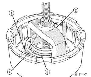
Fig. 185 Compressing Front Clutch Piston Spring
2 - COMPRESSOR TOOL C-3575-A
3 - RETAINER SNAP RING
4 - SPRING RETAINER
Fig. 186 Front Clutch Piston Installation
2 - FRONT CLUTCH RETAINER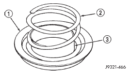
Fig. 187 Clutch Piston Spring Installation
2 - CLUTCH SPRING
3 - PISTON
Fig. 188 Correct Spring Retainer Installed Position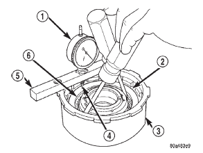
Fig. 189 Measuring Front Clutch Pack Clearance
2 - WAVED SNAP-RING
3 - FRONT CLUTCH
4 - POINTER
5 - GAUGE BAR
6 - PRESSURE PLATE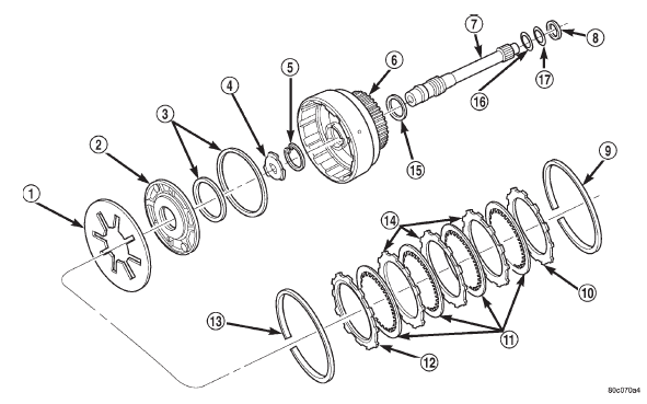
Fig. 190 Rear Clutch Components
2 - REAR CLUTCH PISTON
3 - CLUTCH PISTON SEALS
4 - OUTPUT SHAFT THRUST WASHER (METAL)
5 - INPUT SHAFT SNAP RING
6 - REAR CLUTCH RETAINER
7 - INPUT SHAFT
8 - REAR CLUTCH THRUST WASHER (FIBER)
9 - CLUTCH PACK SNAP RING (SELECTIVE)
10 - TOP PRESSURE PLATE
11 - CLUTCH DISCS (4)
12 - BOTTOM PRESSURE PLATE
13 - WAVE SPRING
14 - CLUTCH PLATES (3)
15 - RETAINER SEAL RING
16 - SHAFT REAR SEAL RING (PLASTIC)
17 - SHAFT FRONT SEAL RING (TEFLON)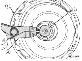
Fig. 191 Removing/Installing Input Shaft Snap-
2 - INPUT SHAFT SNAP RING
3 - SNAP RING PLIERS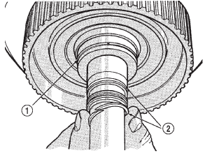
Fig. 192 Rear Clutch Retainer And Input Shaft Seal Ring Installation
2 - INPUT SHAFT SEAL RINGS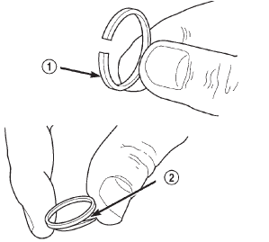
Fig. 193 Input Shaft Seal Ring Identification
2 - TEFLON FRONT SEAL RING (SQUEEZE RING TOGETHER
SLIGHTLY BEFORE INSTALLATION FOR BETTER FIT)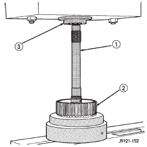
Fig. 194 Pressing Input Shaft Into Rear Clutch Retainer
2 - REAR CLUTCH RETAINER
3 - PRESS RAM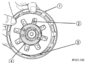
Fig. 195 Piston Spring/Wave Spring Position
2 - PISTON SPRING
3 - WAVE SPRING
4 - CLUTCH PISTON
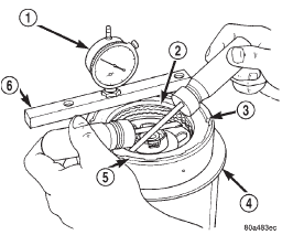
Fig. 196 Checking Rear Clutch Pack Clearance
2 - PRESSURE PLATE
3 - SNAP RING
4 - STAND
5 - REAR CLUTCH
6 - GAUGE BAR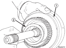
2 - REAR CLUTCH THRUST WASHERPlanetary geartrain/output shaft
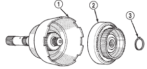
Fig. 198 Front Annulus And Planetary Assembly Removal
2 - FRONT ANNULUS AND PLANETARY ASSEMBLY
3 - PLANETARY SNAP RING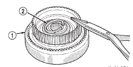
Fig. 199 Front Planetary Snap Ring Removal
2 - PLANETARY SNAP RING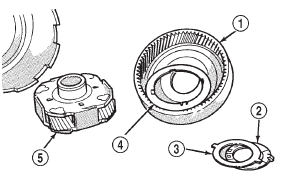
Fig. 200 Front Planetary And Annulus Gear Disassembly
2 - THRUST WASHER
3 - THRUST PLATE
4 - FRONT THRUST WASHER
5 - FRONT PLANETARY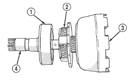
Fig. 201 Removing Driving Shell, Rear Planetary And Rear Annulus
2 - REAR PLANETARY
3 - DRIVING SHELL
4 - OUTPUT SHAFT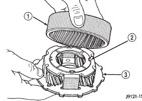
Fig. 202 Assembling Rear Annulus And Planetary Gear
2 - TABBED THRUST WASHER
3 - REAR PLANETARY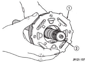
Fig. 203 Installing Rear Annulus And Planetary On Output Shaft
2 - OUTPUT SHAFT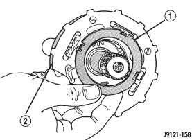
Fig. 204 Installing Rear Planetary Front Thrust Washer
2 - REAR PLANETARY GEAR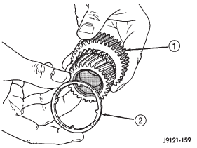
Fig. 205 Installing Spacer On Sun Gear
2 - SUN GEAR SPACER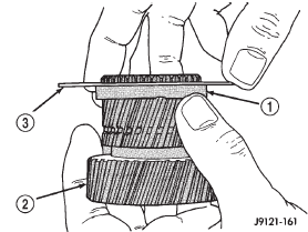
Fig. 206 Installing Driving Shell Front Thrust Plate On Sun Gear
2 - SUN GEAR
3 - THRUST PLATE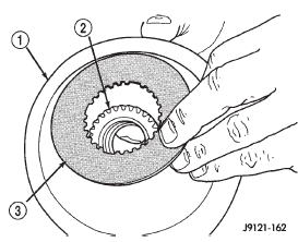
Fig. 207 Installing Driving Shell Rear Thrust Plate
2 - SUN GEAR
3 - REAR THRUST PLATE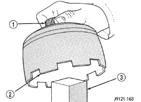
Fig. 208 Supporting Sun Gear On Wood Block
2 - DRIVING SHELL
3 - WOOD BLOCK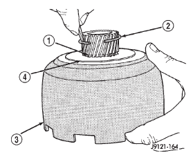
Fig. 209 Installing Sun Gear Lock Ring
2 - SUN GEAR LOCK RING
3 - DRIVING SHELL
4 - REAR THRUST PLATE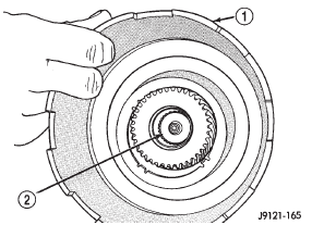
Fig. 210 Installing Assembled Sun Gear And Driving Shell On Output Shaft
2 - OUTPUT SHAFT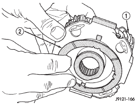
Fig. 211 Installing Rear Thrust Washer On Front Planetary Gear
2 - REAR TABBED THRUST WASHER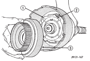
Fig. 212 Installing Front Planetary And Annulus Gears
2 - FRONT THRUST WASHER
3 - FRONT ANNULUS GEAR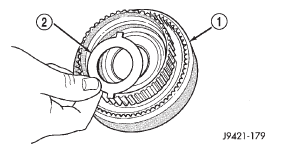
Fig. 213 Positioning Thrust Plate On Front Annulus Support
2 - THRUST PLATE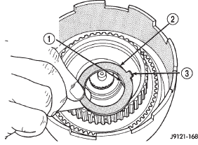
Fig. 214 Installing Front Annulus Thrust Washer
2 - FRONT ANNULUS THRUST WASHER
3 - TAB FACES FRONT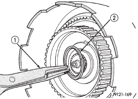
Fig. 215 Installing Front Annulus Snap Ring
2 - FRONT ANNULUS SNAP RING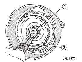
Fig. 216 Installing Planetary Selective Snap Ring
2 - SNAP RING PLIERS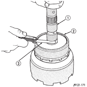
Fig. 217 Checking Planetary Geartrain End
2 - REAR ANNULUS GEAR
3 - FEELER GAUGE
 Oil pump and reaction shaft support
Other materials:
Specifications. Special tools
Specifications
Power steering gear
Steering Gear
Type . . . . . . . . . . . . . . . . . . . . Recirculating Ball
Gear Ratio
RHD . . . . . . . . . . . . . . . . . . . . . . . . . . . . . . . 14:1
LHD . . . . . . . . . . . . . . . . . . . . . . . . . . . . . . . 14:1
Worm Shaft Bearing
Preload . ...

