Jeep Cherokee (XJ): Fuel gauge sending unit. Fuel injector rail/fuel damper-2.5L engine. Fuel injector rail/fuel damper-4.0L engine
The fuel gauge sending unit (fuel level sensor) and
float assembly is located on the side of fuel pump
module (Fig. 27). The fuel pump module is located
within the fuel tank.
1 - FUEL GAUGE FLOAT REMOVAL (1) Remove fuel tank. Refer to Fuel Tank Removal/
Installation.
1 - ELECTRICAL CONNECTOR (2) Remove fuel pump module. Refer to Fuel Pump
Module Removal/Installation.
(3) Remove electrical wire connector at sending
unit terminals.
(4) Press on release tab (Fig. 28) to remove sending
unit from pump module. INSTALLATION (1) Position sending unit to pump module and
snap into place.
(2) Connect electrical connector to terminals.
(3) Install fuel pump module. Refer to Fuel Pump
Module Removal/Installation.
(4) Install fuel tank. Refer to Fuel Tank Removal/
Installation. REMOVAL The fuel damper is not serviced separately. WARNING: THE FUEL SYSTEM IS UNDER CONSTANT
FUEL PRESSURE EVEN WITH ENGINE OFF.
THIS PRESSURE MUST BE RELEASED BEFORE
SERVICING FUEL RAIL.
(1) Remove fuel tank filler tube cap.
(2) Perform Fuel System Pressure Release Procedure
as described in this Group.
(3) Disconnect negative battery cable from battery. (4) Remove air tube at top of throttle body. Note:
Some engine/vehicles may require removal of air
cleaner ducts at throttle body.
(5) Remove injector harness electrical connectors
at each injector. Each injector connector should have
a numerical tag attached identifying its corresponding
cylinder (Fig. 29). If not, identify each connector
before removal.
1 - FUEL DAMPER (6) Disconnect fuel supply line latch clip and fuel
line at fuel rail. Refer to Quick-Connect Fittings in
this group for procedures.
(7) Disconnect throttle cable at throttle body. Refer
to Throttle Cable Removal/Installation in this group
for procedures.
(8) Disconnect speed control cable at throttle body
(if equipped). Refer to Speed Control Cable in Group
8H, Speed Control System for procedures.
(9) Disconnect automatic transmission cable at
throttle body (if equipped).
(10) Remove cable routing bracket (Fig. 29) at
intake manifold.
(11) Remove nut securing crankshaft position sensor
pigtail harness to fuel rail mounting stud.
Remove clamp and harness from fuel rail mounting
stud.
(12) Clean dirt/debris from each fuel injector at
intake manifold.
(13) Remove fuel rail mounting nuts/bolts (Fig.
29).
(14) Remove fuel rail by gently rocking until all
the fuel injectors are out of intake manifold. INSTALLATION (1) Clean each injector bore at intake manifold.
(2) Apply a small amount of clean engine oil to
each injector o-ring. This will aid in installation.
(3) Position tips of all fuel injectors into the corresponding
injector bore in intake manifold. Seat injectors
into manifold.
(4) Install and tighten fuel rail mounting bolts to
11 63 N·m (100 625 in. lbs.) torque.
(5) Position crankshaft position sensor pigtail wire
harness clamp and wire harness to fuel rail mounting
stud. Install nut securing harness to fuel rail
mounting stud.
(6) Connect tagged injector harness connectors to
appropriate injector.
(7) Connect fuel line and fuel line latch clip to fuel
rail. Refer Quick-Connect Fittings in this group for
procedures.
(8) Install protective cap to pressure test port fitting
(if equipped).
(9) Install cable routing bracket to intake manifold.
(10) Connect throttle cable at throttle body.
(11) Connect speed control cable at throttle body (if
equipped).
(12) Connect automatic transmission cable at
throttle body (if equipped).
(13) Install air tube (or duct) at top of throttle
body.
(14) Install fuel tank cap.
(15) Connect negative battery cable to battery.
(16) Start engine and check for fuel leaks. REMOVAL The fuel damper is not serviced separately. WARNING: THE FUEL SYSTEM IS UNDER CONSTANT
FUEL PRESSURE EVEN WITH ENGINE OFF.
THIS PRESSURE MUST BE RELEASED BEFORE
SERVICING FUEL RAIL.
(1) Remove fuel tank filler tube cap.
(2) Perform Fuel System Pressure Release Procedure.
(3) Disconnect negative battery cable from battery.
(4) Remove air tube at top of throttle body. Note:
Some engine/vehicles may require removal of air
cleaner ducts at throttle body. (5) Disconnect electrical connectors at all 6 fuel
injectors. To remove connector refer to (Fig. 30). Push
red colored slider away from injector (1). While pushing
slider, depress tab (2) and remove connector (3)
from injector. The factory fuel injection wiring harness
is numerically tagged (INJ 1, INJ 2, etc.) for
injector position identification. If harness is not
tagged, note wiring location before removal.
(6) Disconnect fuel supply line latch clip and fuel
line at fuel rail. Refer to Quick-Connect Fittings.
(7) Disconnect throttle cable at throttle body. Refer
to Throttle Cable Removal/Installation.
(8) Disconnect speed control cable at throttle body
(if equipped). Refer to Speed Control Cable in Group
8H, Speed Control System.
(9) Disconnect automatic transmission cable at
throttle body (if equipped).
(10) Remove cable routing bracket at intake manifold.
(11) If equipped, remove wiring harnesses at injection
rail studs by removing nuts.
(12) Clean dirt/debris from each fuel injector at
intake manifold.
(13) Remove fuel rail mounting nuts/bolts (Fig.
31).
(14) Remove fuel rail by gently rocking until all
the fuel injectors are out of intake manifold.
1 - INJ. #1 INSTALLATION (1) Clean each injector bore at intake manifold.
(2) Apply a small amount of clean engine oil to
each injector o-ring. This will aid in installation.
(3) Position tips of all fuel injectors into the corresponding
injector bore in intake manifold. Seat injectors
into manifold.
(4) Install and tighten fuel rail mounting bolts to
11 63 N·m (100 625 in. lbs.) torque.
(5) If equipped, connect wiring harnesses to injection
rail studs.
(6) Connect electrical connectors at all fuel injectors.
To install connector, refer to (Fig. 30). Push connector
onto injector (1) and then push and lock red
colored slider (2). Verify connector is locked to injector
by lightly tugging on connector.
(7) Connect fuel line and fuel line latch clip to fuel
rail. Refer Quick-Connect Fittings.. (8) Install protective cap to pressure test port fitting
(if equipped).
(9) Install cable routing bracket to intake manifold.
(10) Connect throttle cable at throttle body.
(11) Connect speed control cable at throttle body (if
equipped).
(12) Connect automatic transmission cable at
throttle body (if equipped).
(13) Install air tube (or duct) at top of throttle
body.
(14) Install fuel tank cap.
(15) Connect negative battery cable to battery.
(16) Start engine and check for fuel leaks.Fuel gauge sending unit
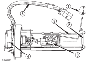
Fig. 27 Fuel Gauge Sending Unit Location
2 - PICK-UP FILTER
3 - FUEL GAUGE SENDING UNIT
4 - FUEL FILTER/FUEL PRESSURE REGULATOR
5 - ELECTRIC FUEL PUMP
6 - PIGTAIL WIRING HARNESS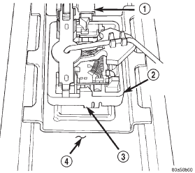
Fig. 28 Fuel Gauge Sending Unit Release Tab
2 - FUEL GAUGE SENDING UNIT
3 - RELEASE TAB
4 - FUEL PUMP MODULEFuel injector rail/fuel damper-2.5L
engine
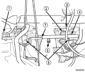
Fig. 29 Fuel Rail Mounting-2.5L Engine
2 - FUEL INJECTOR
3 - NUMBERED TAG
4 - FUEL RAIL
5 - FUEL RAIL MOUNTING BOLTS/NUTS
6 - TEST PORT
7 - CABLE BRACKETFuel injector rail/fuel damper-4.0L
engine
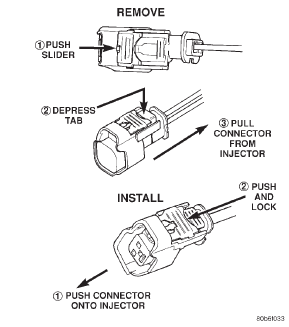
Fig. 30 Remove/Install Fuel Injector Connector-2.5L/4.0L Engine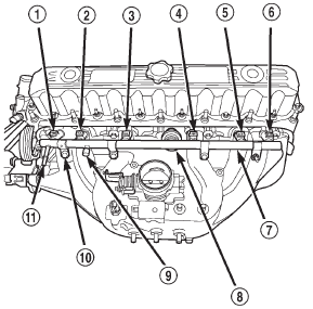
Fig. 31 Fuel Rail Mounting-4.0L Engine
2 - INJ. #2
3 - INJ. #3
4 - INJ. #4
5 - INJ. #5
6 - INJ. #6
7 - FUEL INJECTOR RAIL
8 - FUEL DAMPER
9 - PRESSURE TEST PORT CAP
10 - MOUNTING BOLTS (4)
11 - QUICK-CONNECT FITTING
 Fuel filter/fuel pressure regulator. Fuel pump module. Fuel pump inlet filter
 Fuel injectors. Fuel tank. Fuel tank filler tube cap
Other materials:
Maintenance-Free Battery. Air Conditioner Maintenance. Body Lubrication
Maintenance-Free Battery
Your vehicle is equipped with a maintenance-free battery.
You will never have to add water, nor is periodic maintenance
required.
WARNING!
Battery fluid is a corrosive acid solution and can
burn or even blind you. Do not allow battery fluid
to contact your eyes, ...
