Jeep Cherokee (XJ): Instrument panel cigar lighter. Cigar lighter relay. Instrument panel power outlet
For complete circuit diagrams, refer to Horn/Cigar
Lighter in the Contents of Group 8W - Wiring
Diagrams. WARNING: ON VEHICLES EQUIPPED WITH AIRBAGS,
REFER TO GROUP 8M - PASSIVE
RESTRAINT SYSTEMS BEFORE ATTEMPTING ANY
STEERING WHEEL, STEERING COLUMN, OR
INSTRUMENT PANEL COMPONENT DIAGNOSIS OR
SERVICE. FAILURE TO TAKE THE PROPER PRECAUTIONS
COULD RESULT IN ACCIDENTAL AIRBAG
DEPLOYMENT AND POSSIBLE PERSONAL
INJURY. (1) Remove the cigar lighter knob and element
from the cigar lighter receptacle shell. Check for continuity
between the inside circumference of the cigar
lighter receptacle shell and a good ground. there
should be continuity. If OK, go to Step 2. If not OK,
go to Step 3.
(2) Turn the ignition switch to the On position.
Check for battery voltage at the insulated contact
located at the back of the cigar lighter receptacle
shell. If OK, replace the faulty cigar lighter knob and
element. If not OK, go to Step 3.
(3) Turn the ignition switch to the Off position.
Disconnect and isolate the battery negative cable.
Remove the instrument panel accessory switch bezel.
Check for continuity between the ground circuit cavity
of the cigar lighter wire harness connector and a
good ground. There should be continuity. If OK, go to
Step 4. If not OK, repair the open ground circuit to
ground as required.
(4) Connect the battery negative cable. Turn the
ignition switch to the Accessory or On positions.
Check for battery voltage at the cigar lighter relay output circuit cavity of
the cigar lighter wire harness
connector. If OK, replace the faulty cigar lighter
receptacle (instrument panel accessory switch bezel
unit). If not OK, refer to Cigar Lighter Relay in
the Diagnosis and Testing section of this group for
further diagnosis. The cigar lighter relay (Fig. 3) is located in the
junction block, on the right cowl side inner panel
below the instrument panel in the passenger compartment.
For complete circuit diagrams, refer to
Horn/Cigar Lighter in the Contents of Group 8W -
Wiring Diagrams.
WARNING: ON VEHICLES EQUIPPED WITH AIRBAGS,
REFER TO GROUP 8M - PASSIVE
RESTRAINT SYSTEMS BEFORE ATTEMPTING ANY
STEERING WHEEL, STEERING COLUMN, OR
INSTRUMENT PANEL COMPONENT DIAGNOSIS OR
SERVICE. FAILURE TO TAKE THE PROPER PRECAUTIONS
COULD RESULT IN ACCIDENTAL AIRBAG
DEPLOYMENT AND POSSIBLE PERSONAL
INJURY.
(1) Remove the cigar lighter relay from the junction
block. Refer to Cigar Lighter Relay in the
Removal and Installation section of this group for the
procedures.
(2) A relay in the de-energized position should
have continuity between terminals 87A and 30, and
no continuity between terminals 87 and 30. If OK, go
to Step 3. If not OK, replace the faulty relay.
(3) Resistance between terminals 85 and 86 (electromagnet)
should be 75 6 5 ohms. If OK, go to Step
4. If not OK, replace the faulty relay.
(4) Connect a battery to terminals 85 and 86.
There should now be continuity between terminals
30 and 87, and no continuity between terminals 87A
and 30. If OK, perform the Relay Circuit Test that
follows. If not OK, replace the faulty relay. RELAY CIRCUIT TEST (1) The relay common feed terminal cavity (30) of
the junction block is connected to battery voltage and
should be hot at all times. Check for battery voltage
at the fused B(+) circuit cavity of the accessory relay
wire harness connector. If OK, go to Step 2. If not
OK, repair the fused B(+) circuit to the fuse in the
junction block as required.
(2) The relay normally closed terminal (87A) is
connected to terminal 30 in the de-energized position,
but is not used for this application. Go to Step 3.
(3) The relay normally open terminal (87) is connected
to the common feed terminal (30) in the energized
position. This terminal supplies battery voltage
to the cigar lighter when the relay is energized by the ignition switch. There
should be continuity
between the junction block cavity for relay terminal
87 and the cigar lighter relay output circuit cavity of
the cigar lighter wire harness connector at all times.
If OK, go to Step 4. If not OK, repair the open cigar
lighter relay output circuit to the cigar lighter wire
harness connector as required.
(4) The coil battery terminal (86) is connected to
the electromagnet in the relay. It receives battery
feed to energize the cigar lighter relay when the ignition
switch is in the Accessory or On positions. Turn
the ignition switch to the On position. Check for battery
voltage at the fused ignition switch output (acc/
run) circuit cavity for relay terminal 86 in the
junction block. If OK, go to Step 5. If not OK, repair
the open fused ignition switch output (acc/run) circuit
to the ignition switch as required.
(5) The coil ground terminal (85) is connected to
the electromagnet in the relay. The junction block
cavity for this terminal should have continuity to
ground at all times. If not OK, repair the open
ground circuit to ground as required.
For complete circuit diagrams, refer to Horn/Cigar
Lighter in the Contents of Group 8W - Wiring
Diagrams. WARNING: ON VEHICLES EQUIPPED WITH AIRBAGS,
REFER TO GROUP 8M - PASSIVE
RESTRAINT SYSTEMS BEFORE ATTEMPTING ANY
STEERING WHEEL, STEERING COLUMN, OR
INSTRUMENT PANEL COMPONENT DIAGNOSIS OR
SERVICE. FAILURE TO TAKE THE PROPER PRECAUTIONS
COULD RESULT IN ACCIDENTAL AIRBAG
DEPLOYMENT AND POSSIBLE PERSONAL
INJURY.
(1) Check the fused B(+) fuse in the junction block.
If OK, go to Step 2. If not OK, repair the shorted circuit
or component as required and replace the faulty
fuse.
(2) Check for battery voltage at the fused B(+) fuse
in the junction block. If OK, go to Step 3. If not OK,
repair the open fused B(+) circuit to the Power Distribution
Center (PDC) as required.
(3) Remove the plastic protective cap from the
power outlet receptacle. Check for continuity between
the inside circumference of the power outlet receptacle
and a good ground. There should be continuity. If
OK, go to Step 4. If not OK, go to Step 5.
(4) Check for battery voltage at the insulated contact
located at the back of the power outlet receptacle.
If not OK, go to Step 5.
(5) Disconnect and isolate the battery negative
cable. Remove the instrument panel accessory switch
bezel. Check for continuity between the ground circuit
cavity of the power outlet wire harness connector
and a good ground. There should be continuity. If
OK, go to Step 6. If not OK, repair the open ground
circuit to ground as required.
(6) Connect the battery negative cable. Check for
battery voltage at the fused B(+) circuit cavity of the
power outlet wire harness connector. If OK, replace
the faulty power outlet receptacle (instrument panel
accessory switch bezel unit). If not OK, repair the
open fused B(+) circuit to the junction block fuse as
required.Instrument panel cigar lighter
Cigar lighter relay
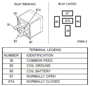
Fig. 3 Cigar Lighter RelayInstrument panel power outlet


Other materials:
Fuses
WARNING!
When replacing a blown fuse, always use an appropriate
replacement fuse with the same amp rating as
the original fuse. Never replace a fuse with another fuse of higher amp
rating. Never replace a blown
fuse with metal wires or any other material. Failure
to use proper fuses m ...