Jeep Cherokee (XJ): Piston ring-fitting
(1) Carefully clean the carbon from all ring grooves. Oil drain openings in the oil ring groove and pin boss must be clear. DO NOT remove metal from the grooves or lands. This will change ring-to-groove clearances and will damage the ring-to-land seating.
(2) Be sure the piston ring grooves are free of nicks and burrs.
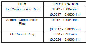
(3) Measure the ring side clearance with a feeler gauge fitted snugly between the ring land and ring (Fig. 21) (Fig. 22). Rotate the ring in the groove. It must move freely around circumference of the groove.
(4) Place ring in the cylinder bore and push down with inverted piston to position near lower end of the ring travel. Measure ring gap with a feeler gauge fitting snugly between ring ends (Fig. 23).
Fig. 19 Moly Coated Piston
1 - MOLY COATED
2 - MOLY COATED
Fig. 20 Bore Gauge
1 - FRONT
2 - BORE GAUGE
3 - CYLINDER BORE
4 - 49.5 MM (1-15/16 in)
PISTON SIZE CHART
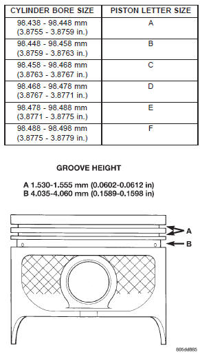
Fig. 21 Piston Dimensions
(5) The oil control rings are symmetrical, and can be installed with either side up. It is not necessary to use a tool to install the upper and lower rails. Insert oil rail spacer first, then side rails.
(6) The two compression rings are different and cannot be interchanged. The top compression ring can be identified by the shiny coating on the outer sealing surface and can be installed with either side up. (Fig. 24).
Fig. 22 Ring Side Clearance Measurement
1 - FEELER GAUGE
RING SIDE CLEARANCE CHART
(7) The second compression ring has a slight chamfer on the bottom of the inside edge and a dot on the top for correct installation (Fig. 25).
(8) Using a ring installer, install the second compression ring with the dot facing up (Fig. 25) (Fig.
27).
(9) Using a ring installer, install the top compression ring (either side up).
Ring Gap Orientation
- Position the gaps on the piston as shown (Fig. 28).
- Oil spacer - Gap on center line of piston skirt.
- Oil rails - gap 180 apart on centerline of piston pin bore.
Fig. 23 Gap Measurement
1 - FEELER GAUGE
RING GAP MEASUREMENT CHART
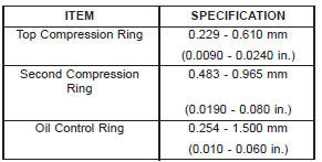
Fig. 24 Top Compression ring identification
1 - TOP COMPRESSION RING
- No. 2 Compression ring - Gap 180 from top oil rail gap.
- No. 1 Compression ring - Gap 180 from No. 2 compression ring gap
Fig. 25 Second Compression Ring Identification
1 - SECOND COMPRESSION RING
2 - CHAMFER
3 - ONE DOT
Fig. 26 Compression Ring Chamfer Location
1 - TOP COMPRESSION RING
2 - SECOND COMPRESSION RING
3 - PISTON
4 - CHAMFER
Fig. 27 Compression Ring Installation
1 - COMPRESSION RING
2 - RING EXPANDER RECOMMENDED
Fig. 28 Ring Gap Orientation
1 - TOP COMPRESSION RING
2 - BOTTOM COMPRESSION RING
3 - TOP OIL CONTROL RAIL
4 - OIL RAIL SPACER
5 - BOTTOM OIL CONTROL RAIL
6 - IMAGINARY LINE PARALLEL TO PISTON PIN
7 - IMAGINARY LINE THROUGH CENTER OF PISTON SKIRT
 Valve timing. Valve service. Piston fitting
 Fitting connecting rod bearings. Fitting crankshaft main bearings. Form-in-place gaskets
Other materials:
Diagnosis and testing
Power seat system
Before any testing of the power seat system is
attempted, the battery should be fully-charged and
all wire harness connections and pins cleaned and
tightened to ensure proper continuity and grounds.
For circuit descriptions and diagrams, refer to 8W-63
- Power Seat in Group ...