Jeep Cherokee (XJ): Power steering pump
DESCRIPTION Hydraulic pressure for the power steering system
is provided by a belt driven power steering pump
(Fig. 1). The pump shaft has a pressed-on high
strength plastic drive pulley that is belt driven by
the crankshaft pulley. The reservoir is attached to
the pump body with spring clips on the 4.0L engine.
A remote pump reservoir is used on the 2.5L engine
mounted to the fan shroud. The power steering pump
is connected to the steering gear by the pressure and
return hoses. OPERATION The power steering pump is a constant flow rate
and displacement, vane-type pump. The pump internal
parts operate submerged in fluid. The flow control
orifice is part of the high pressure line fitting.
The pressure relief valve inside the flow control valve
limits the pump pressure.
NOTE: Power steering pumps have different pressure
rates and are not interchangeable with other
pumps. DESCRIPTION The hose consists of two metal ends and rubber
center section that contains a tuning cable.
1 - CAP OPERATION Power steering pressure line, is used to transfer
high pressure power steering fluid, from the power
steering pump to the power steering gear. DESCRIPTION Power steering return line is a hose which is
clamped at the pump and the gear. OPERATION Power steering return line, is used to transfer low
pressure power steering fluid, from the power steering
gear to the power steering pump. The following procedure is used to test the operation
of the power steering system on the vehicle. This
test will provide the gallons per minute (GPM) or
flow rate of the power steering pump along with the
maximum relief pressure. Perform test any time a
power steering system problem is present. This test
will determine if the power steering pump or power
steering gear is not functioning properly. The following
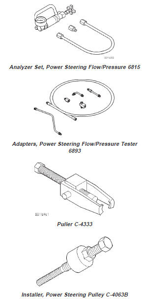
pressure and flow test is performed using Power
Steering Analyzer Tool Kit 6815 (Fig. 2) and Adapter
Kit 6893.
1 - TUBE FLOW AND PRESSURE TEST (1) Check the power steering belt to ensure it is in
good condition and adjusted properly.
(2) Connect pressure gauge hose from the Power
Steering Analyzer to Tube 6865.
(3) Connect Adapter 6826 to Power Steering Analyzer
test valve end.
(4) Disconnect high pressure hose at the pump.
Use a container for dripping fluid.
(5) Connect Tube 6865 to the pump hose fitting.
(6) Connect the power steering hose from the
steering gear to Adapter 6826.
(7) Open the test valve completely.
(8) Start engine and let idle long enough to circulate
power steering fluid through flow/pressure test
gauge and to get air out of the fluid. Then shut off
engine.
(9) Check fluid level, add fluid as necessary. Start
engine again and let idle.
(10) Gauge should read below 862 kPa (125 psi), if
above, inspect the hoses for restrictions and repair as
necessary. The initial pressure reading should be in
the range of 345-552 kPa (50-80 psi).
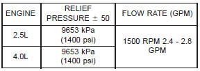
(11) Increase the engine speed to 1500 RPM and
read the flow meter. The reading should be 2.4 - 2.8
GPM, if the reading is below this specification the
pump should be replaced.
CAUTION: The next step involves testing maximum
pump pressure output and flow control valve operation.
Do not leave valve closed for more than three
seconds as the pump could be damaged.
(12) Close valve fully three times and record highest
pressure indicated each time. All three readings
must be above specifications and within
345 kPa (50 psi) of each other. (13) Open the test valve, turn steering wheel
extreme left and right positions against the stops.
Record the highest indicated pressure at each position.
Compare readings to specifications. If highest
output pressures are not the same against either
stop, the gear is leaking internally and must be
repaired.
CAUTION: Do not force the pump to operate
against the stops for more than 2 to 3 seconds at a
time because, pump damage will result. PUMP SPECIFICATIONS
POWER STEERING PUMP - INITIAL
OPERATION WARNING: THE FLUID LEVEL SHOULD BE
CHECKED WITH ENGINE OFF TO PREVENT INJURY
FROM MOVING COMPONENTS.
CAUTION: Use MOPAR Power Steering Fluid or
equivalent. Do not use automatic transmission fluid
and do not overfill.
Wipe filler cap clean, then check the fluid level.
The dipstick should indicate COLD when the fluid is
at normal ambient temperature.
(1) Fill the pump fluid reservoir to the proper level
and let the fluid settle for at least two minutes.
(2) Start the engine and let run for a few seconds
then turn engine off.
(3) Add fluid if necessary. Repeat the above procedure
until the fluid level remains constant after running
the engine.
(4) Raise the front wheels off the ground.
(5) Slowly turn the steering wheel right and left,
lightly contacting the wheel stops at least 20 times.
(6) Check the fluid level add if necessary.
(7) Lower the vehicle, start the engine and turn
the steering wheel slowly from lock to lock.
(8) Stop the engine and check the fluid level and
refill as required.
(9) If the fluid is extremely foamy or milky looking,
allow the vehicle to stand a few minutes and
repeat the procedure.
CAUTION: Do not run a vehicle with foamy fluid for
an extended period. This may cause pump damage. NOTE: The power steering pump is mounted in the
same position on LHD and RHD vehicles. On 4.0L
RHD vehicles the front bracket is different. The service
procedures are the same. REMOVAL (1) Remove serpentine drive belt, refer to Group 7
Cooling.
(2) Remove pressure and return hoses from pump,
and drain pump.
(3) Remove 3 pump mounting bolts through pulley
access holes.
(4) Loosen the 3 pump bracket bolts (Fig. 3) and
(Fig. 4).
(5) Tilt pump downward and remove from engine.
(6) Remove pulley from pump. INSTALLATION (1) Install pulley on pump.
(2) Install pump on engine.
(3) Tighten pump bracket bolts to 47 N·m (35 ft.
lbs.).
(4) Install 3 pump mounting bolts and tighten to
27 N·m (20 ft. lbs.).
(5) Install the pressure and return hoses to pump.
(6) Install drive belt, refer to Group 7 Cooling.
(7) Add power steering fluid and perform Power
Steering Pump Initial Operation. REMOVAL (1) Remove the hoses from the bottom of the reservoir
and drain the reservoir.
(2) Remove the push-in fastener from the top of
the fan shroud.
(3) Slide reservoir up off the fan shroud. INSTALLATION (1) Slide reservoir down onto fan shroud.
(2) Install the push-in fastener in the top of fan
shroud.
1 - PUMP BRACKET (3) Install the pump hoses.
(4) Fill reservoir to proper level. Refer to Power
Steering Pump Initial Operation. DISASSEMBLY (1) Remove pump assembly.
(2) Remove pulley from pump with Puller C-4333
or equivalent puller (Fig. 5). ASSEMBLY NOTE: The pulley is marked front for installation.
(1) Replace pulley if bent, cracked, or loose.
(2) Install pulley on pump with Installer C-4063-B
or equivalent installer (Fig. 6). The pulley must be
flush with the end of the shaft. Ensure the tool and
pulley are aligned with the pump shaft.
(3) Install pump assembly.
(4) With Serpentine Belt, run engine until warm (5
min.) and note any belt chirp. If chirp exists, move
pulley outward approximately 0.5 mm (0.020 in.). If
noise increases, press on 1.0 mm (0.040 in.). Be
careful that pulley does not contact mounting
bolts. DISASSEMBLY (1) Remove power steering pump.
(2) Clean exterior of pump.
(3) Clamp the pump body in a soft jaw vice.
(4) Pry up tab and slide the retaining clips off (Fig.
7).
NOTE: Use new retaining clips for installation.
(5) Remove fluid reservoir from pump body.
Remove and discard O-ring seal. ASSEMBLY (1) Lubricate new O-ring Seal with Mopar Power
Steering Fluid or equivalent.
1 - BRACKET
1 - POWER STEERING PUMP DRIVE PULLEY (2) Install O-ring seal in housing.
(3) Install reservoir onto housing.
(4) Slide and tap in new reservoir retainer clips
until tab locks to housing.
1 - POWER STEERING PUMP DRIVE PULLEY (5) Install power steering pump.
(6) Add power steering fluid, refer to Pump Initial
Operation.
1 - RESERVOIR TORQUE CHART DESCRIPTION TORQUE Power Steering Pump Bracket to Pump . . . . . . . . . . 28 N·m (21 ft. lbs.) POWER STEERING PUMP
Description and operation
Power steering pump
Power steering pressure line
Fig. 1 Pump With Integral Reservoir
2 - FLUID RESERVOIR (TYPICAL)
3 - HIGH-PRESSURE FITTING
4 - DRIVE PULLEY
5 - PUMP BODY
6 - RESERVOIR CLIPPower steering return line
Diagnosis and testing
Power flow and pressure
Fig. 2 Power Steering Analyzer
2 - ADAPTER FITTINGS
3 - ANALYZER
4 - GAUGE HOSE
Pump leakage diagnosis
Service procedures
Removal and installation
Power steering pump
Pump reservoir-2.5L
Fig. 3 Pump Mounting LHD
2 - PUMP ASSEMBLY 2.5L
3 - PUMP ASSEMBLY 4.0LDisassembly and assembly
Pump pulley
Pump reservoir
Fig. 4 Pump Mounting 4.0L RHD
2 - PUMP ASSEMBLY
Fig. 5 Pulley Removal
2 - SPECIAL TOOL C-4333
Fig. 6 Pulley Installation
2 - SPECIAL TOOL C-4063-B
Fig. 7 Pump Reservoir Clips
2 - RETAINING CLIPSSpecifications
Bracket to Engine . . . . . . . . . 47 N·m (35 ft. lbs.)
Flow Control Valve . . . . . . . . 75 N·m (55 ft. lbs.)
Pressure Line . . . . . . . . . . . . . 28 N·m (21 ft. lbs.)Special tools


Other materials:
General Information
This device complies with FCC rules Part 15 and Industry
Canada RSS-210. Operation is subject to the following
two conditions:
1. This device may not cause harmful interference.
2. This device must accept any interference that may be
received including interference that may cause undesired
o ...