Jeep Cherokee (XJ): Removal and installation
(1) Disconnect and isolate the battery negative
cable.
(2) Remove the screws that secure the front door
trim panel to the inner door panel (Fig. 4).
(3) Using a trim stick or another suitable wide
flat-bladed tool, gently pry the front door trim panel
away from the door around the perimeter to release
the trim panel retainers.
NOTE: To aid in the removal of the trim panel, start
at the bottom of the panel.
(4) Lift the front door trim panel upwards and
away from the inner door panel far enough to disengage
the top of the panel from the inner belt weatherstrip.
(5) Pull the front door trim panel away from the
inner door panel far enough to access the inside door
latch release and lock linkage rods near the back of
the inside door remote controls.
(6) Unsnap the plastic retainer clips from the
inside door remote control ends of the latch release
and lock linkage rods, and remove the rod ends from
the inside door remote controls.
1 - U-NUT (7) Unplug the wire harness connectors from the
door module.
(8) Remove the trim panel from the front door.
(9) Remove the three screws that secure the door
module to the front door trim panel (Fig. 5).
1 - INSIDE DOOR LATCH AND LOCK REMOTE CONTROLS (10) Remove the door module from the front door
trim panel.
(11) Reverse the removal procedures to install.
Tighten the mounting screws to 2.2 N·m (20 in. lbs.). (1) Disconnect and isolate the battery negative
cable. (2) Remove the screws that secure the door trim
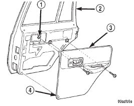
panel to the inner door panel (Fig. 6).
1 - U-NUT (3) Using a trim stick or another suitable wide
flat-bladed tool, gently pry the rear door trim panel
away from the door around the perimeter to release
the trim panel retainers.
NOTE: To aid in the removal of the trim panel, start
at the bottom of the panel.
(4) Lift the rear door trim panel upwards and
away from the inner door panel far enough to disengage
the top of the panel from the inner belt weatherstrip.
(5) Pull the rear door trim panel away from the
inner door panel far enough to access the inside door
latch release and lock linkage rods near the back of
the inside door remote controls.
(6) Unsnap the plastic retainer clips from the
inside door remote control ends of the latch release
and lock linkage rods, and remove the rod ends from
the inside door remote controls.
(7) Unplug the wire harness connector from the
rear door power window switch.
(8) Remove the trim panel from the rear door.
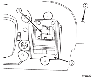
(9) With a small thin-bladed screwdriver, gently
pry the snap clips at the sides of the power window
switch receptacle on the back of the rear door trim
panel and pull the switch out of the receptacle (Fig.
7).
(10) Reverse the removal procedures to install. Be
certain that both of the switch snap retainers in the
receptacle on the back of the trim panel are fully
engaged.
1 - REAR DOOR POWER WINDOW SWITCH FRONT DOOR The front door power window motor and mechanism
is integral to the front door power window regulator
unit. If the front door power window motor or
mechanism is faulty or damaged, the entire power
window regulator unit must be replaced. Refer to
Group 23 - Body for the front door window regulator
service procedures. REAR DOOR The rear door power window motor and mechanism
is integral to the rear door power window regulator
unit. If the rear door power window motor or mechanism
is faulty or damaged, the entire power window
regulator unit must be replaced. Refer to Group 23 -
Body for the rear door window regulator service
procedures.Door module

Fig. 4 Front Door Trim Panel Remove/Install
2 - DOOR
3 - TRIM PANEL
4 - PUSH-IN FASTENER
Fig. 5 Door Module Remove/Install
2 - CONNECTOR 1 RECEPTACLE
3 - DOOR MODULE
4 - CONNECTOR 2 RECEPTACLE
5 - SCREWS
6 - DOOR TRIM PANELPower window switch

Fig. 6 Rear Door Trim Panel Remove/Install
2 - REAR DOOR
3 - TRIM PANEL
4 - PUSH-IN FASTENER
Fig. 7 Rear Door Power Window Switch Remove/Install
2 - TRIM PANEL
3 - SWITCH RECEPTACLEPower window motor
Other materials:
Display. Voice. Safety & Driving Assistance
Display
After pressing the "Display" button on the touchscreen
the following settings will be available.
Display Mode
When in this display you may select the "Auto" or
"Manual" display settings. To change Mode status, press and release the "Auto"
or "Manual" button on the
touchscreen. Th ...


