Jeep Cherokee (XJ): Removal and installation
This procedure covers removal of the stand-alone
type power mirror switch. Vehicles with power windows
and power locks have a power mirror switch
which is integral to the Driver Door Module (DDM).
See Door Module in this group for the DDM-type
power mirror switch service procedures.
(1) Disconnect and isolate the battery negative
cable.
(2) Using a trim stick or another suitable wide
flat-bladed tool, gently pry around the perimeter
edge of the switch to release the snap clips that
secure the switch to the trim panel (Fig. 4).
(3) Pull the power mirror switch away from the
trim panel far enough to access the wire harness connector.
(4) Unplug the power mirror switch from the wire
harness connector.
(5) Reverse the removal procedures to install. (1) Disconnect and isolate the battery negative
cable.
(2) Remove the screws that secure the front door
trim panel to the inner door panel (Fig. 5).
(3) Using a trim stick or another suitable wide
flat-bladed tool, gently pry the front door trim panel
away from the door around the perimeter to release
the trim panel retainers.
NOTE: To aid in the removal of the trim panel, start
at the bottom of the panel.
1 - STAND-ALONE POWER MIRROR SWITCH (4) Lift the front door trim panel upwards and
away from the inner door panel far enough to disengage
the top of the panel from the inner belt weatherstrip.
1 - U-NUT (5) Pull the front door trim panel away from the
inner door panel far enough to access the inside door
latch release and lock linkage rods near the back of
the inside door remote controls.
(6) Unsnap the plastic retainer clips from the
inside door remote control ends of the latch release
and lock linkage rods, and remove the rod ends from
the inside door remote controls.
(7) Unplug the wire harness connectors from the
door module.
(8) Remove the trim panel from the front door.
(9) Remove the three screws that secure the door
module to the front door trim panel (Fig. 6).
(10) Remove the door module from the front door
trim panel.
(11) Reverse the removal procedures to install.
Tighten the mounting screws to 2.2 N·m (20 in. lbs.) (1) Disconnect and isolate the battery negative
cable.
(2) If the vehicle is so equipped, remove the manual
window regulator crank handle with a removal
tool (Fig. 7).
(3) Remove the screws that secure the front door
trim panel to the inner door panel (Fig. 8) or (Fig. 9).
(4) Using a trim stick or another suitable wide
flat-bladed tool, gently pry the front door trim panel
away from the door around the perimeter to release
the trim panel retainers.
1 - INSIDE DOOR LATCH AND LOCK REMOTE CONTROLS
1 - DOOR HANDLE REMOVAL TOOL NOTE: To aid in the removal of the trim panel, start
at the bottom of the panel.
(5) Lift the front door trim panel upwards and
away from the inner door panel far enough to disengage
the top of the panel from the inner belt weatherstrip.
(6) Pull the front door trim panel away from the
inner door far enough to access the inside door latch
release and lock linkage rods near the back of the
inside door remote controls.
(7) Unsnap the plastic retainer clips from the
inside door remote control ends of the latch release
and lock linkage rods, and remove the rod ends from
the inside door remote controls.
1 - U-NUT
1 - U-NUT (8) Unplug the wire harness connectors from the
door power switch module or, on the driver side only,
the stand-alone power mirror switch.
(9) Set the front door trim panel aside.
(10) Remove the one screw that secures the front
door flag trim to the inner door panel (Fig. 10).
(11) Using a trim stick or another suitable wide
flat-bladed tool, gently pry the door flag trim away from the
inner door to release the trim panel
retainer
1 - FRONT DOOR (12) Unplug the power mirror wire harness connector.
(13) Remove the three screws that secure the
power mirror to the inner door panel (Fig. 11).
(14) Unseat the power mirror wire harness grommet
by pushing it out through the hole in the door
flag from the inside.
1 - SIDE VIEW MIRROR (15) Pull the mirror and seal from the outside of
the door while feeding the wire harness, grommet,
and connector out through the hole from the inside of
the door.
(16) Reverse the removal procedures to install.
Tighten the mirror mounting screws to 4.3 N·m (38
in. lbs.). Tighten the door trim mounting screws to
2.2 N·m (20 in. lbs.).Power mirror switch
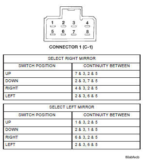
Fig. 2 Driver Door Module Power Mirror Switch ContinuityDoor module
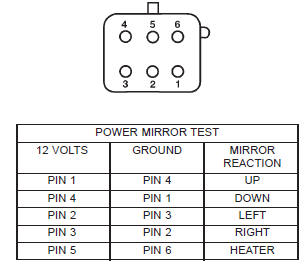
Fig. 3 Power Mirror Test
Fig. 4 Stand-Alone Power Mirror Switch Remove/Install
2 - CONNECTOR
3 - DOOR TRIM PANEL
Fig. 5 Front Door Trim Panel Remove/Install
2 - DOOR
3 - TRIM PANEL
4 - PUSH-IN FASTENERPower mirror
Fig. 6 Door Module Remove/Install
2 - CONNECTOR 1 RECEPTACLE
3 - DOOR MODULE
4 - CONNECTOR 2 RECEPTACLE
5 - SCREWS
6 - DOOR TRIM PANEL
Fig. 7 Window Regulator Crank Handle Remove - Typical
2 - WINDOW CRANK
Fig. 8 Front Door Trim Panel Remove/Install - Manual Window
2 - DOOR
3 - TRIM PANEL
4 - WINDOW CRANK
5 - SPACER
6 - PUSH-IN FASTENER
Fig. 9 Front Door Trim Panel Remove/Install - Power
Window
2 - DOOR
3 - TRIM PANEL
4 - PUSH-IN FASTENER
Fig. 10 Front Door Flag Trim Panel Remove/Install
2 - DOOR FLAG TRIM PANEL
3 - RETAINER
4 - SCREW
5 - UPPER SPEAKER WIRE HARNESS
Fig. 11 Power Mirror Remove/Install
2 - WIRE HARNESS
3 - SEAL
4 - GROMMET
5 - DOOR


Other materials:
Tire pressure monitor system (tpms)
The Tire Pressure Monitor System (TPMS) will warn the
driver of a low tire pressure based on the vehicle recommended
cold placard pressure.
The tire pressure will vary with temperature by approximately
1 psi (7 kPa) for every 12F (6.5C). This means
that when the outside temperature decreases, ...