Jeep Cherokee (XJ): Diagnosis and testing
POWER MIRROR SYSTEM
For circuit descriptions and diagrams, refer to 8W-62 - Power Mirrors in Group 8W - Wiring Diagrams.
(1) Check the fuse in the junction block. If OK, go to Step 2. If not OK, repair the shorted circuit or component as required and replace the faulty fuse.
(2) Turn the ignition switch to the On position.
Check for battery voltage at the fuse in the junction block. If OK, go to Step 3. If not OK, repair the open circuit to the ignition switch as required.
(3) If the problem being diagnosed is inoperative illumination of the power mirror switch directional buttons for the Driver Door Module (DDM)-type switch, proceed as follows. If not, go to Step 5. Check the power window circuit breaker in the junction block. If OK, go to Step 4. If not OK, replace the faulty circuit breaker.
(4) Turn the ignition switch to the Off position.
Disconnect and isolate the battery negative cable.
Remove the driver side front door trim panel and unplug the DDM wire harness connectors. Connect the battery negative cable. Turn the ignition switch to the On position. Check for battery voltage at the fused ignition switch output circuit cavity of the 12-way DDM wire harness connector. If OK, replace the faulty DDM. If not OK, repair the open circuit to the power window circuit breaker in the junction block as required.
(5) If the problem being diagnosed is an inoperative power mirror electric heating grid, proceed as follows. If not, go to Step 8. Disconnect and isolate the battery negative cable. Remove the front door trim panel on the side of the vehicle with the inoperative mirror heating grid. Unplug the wire harness connector at the mirror. Check for continuity between the ground circuit cavity in the body half of the power mirror wire harness connector and a good ground. If OK, go to Step 6. If not OK, repair the open circuit to ground as required.
(6) Connect the battery negative cable. Turn the ignition switch to the On position. Turn on the rear window defogger system. Check for battery voltage at the rear window defogger relay output circuit cavity in the body half of the power mirror wire harness connector. If OK, go to Step 7. If not OK, repair the open circuit to the rear window defogger relay as required.
(7) Check for continuity between the ground circuit and the rear window defogger relay output circuit cavities in the mirror half of the power mirror wire harness connector. There should be continuity. If not OK, replace the faulty power mirror. If OK, check the resistance through the electric heating grid circuit.
Correct resistance through the electric heating grid should be from 10 to 16 ohms when measured at an ambient temperature of 21 C (70 F). If not OK, replace the faulty power mirror.
(8) Disconnect and isolate the battery negative cable. Remove the stand-alone power mirror switch from the driver side front door trim panel or, with a DDM-mounted switch, remove the driver side front door trim panel. Unplug the wire harness connector from the stand-alone switch or the 8-way wire harness connector from the DDM. Connect the battery negative cable. Turn the ignition switch to the On position. Check for battery voltage at the fused ignition switch output circuit cavity of the stand-alone switch wire harness connector or the 8-way DDM wire harness connector. If OK, go to Step 9. If not OK, repair the open circuit to the junction block as required.
(9) Turn the ignition switch to the Off position.
Disconnect and isolate the battery negative cable.
Check for continuity between the ground circuit cavity of the stand-alone switch wire harness connector or the 8-way DDM wire harness connector and a good ground. There should be continuity. If OK, go to Step 10. If not OK, repair the circuit to ground as required.
(10) Check the stand-alone power mirror switch or DDM-mounted power mirror switch continuity as shown in (Fig. 1) or (Fig. 2). If OK, go to Step 11. If not OK, replace the faulty stand-alone power mirror switch or the faulty DDM.
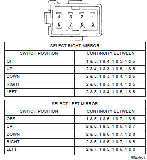
Fig. 1 Stand-Alone Power Mirror Switch Continuity
(11) Connect the battery negative cable. Use two jumper wires, one connected to a 12-volt battery feed, and the other connected to a good body ground. See the Power Mirror Test chart for the correct jumper wire connections at the mirror half of the power mirror wire harness connector (Fig. 3). If the mirror reactions are OK, repair the wire harness between the mirror and the stand-alone power mirror switch or the DDM as required. If the mirror reactions are not OK, replace the faulty power outside mirror assembly.


Other materials:
Compressor clutch. Compressor clutch relay. Condenser
Compressor clutch
DESCRIPTION
The compressor clutch assembly consists of a stationary
electromagnetic coil, a hub bearing and pulley
assembly, and a clutch plate (Fig. 2). The
electromagnetic coil unit and the hub bearing and
pulley assembly are each retained on the nose of the
compressor fron ...