Jeep Cherokee (XJ): Removal and installation
(1) Disconnect and isolate the battery negative
cable.
(2) Remove the two screws located forward of the
display module that secure the overhead console to
the upper windshield opening reinforcement (Fig. 3).
(3) To release the overhead console from the rear
mounting bracket, use your fingertips to gently pull
the sides of the overhead console housing outward
near the rear mounting bracket.
(4) Move the overhead console forward to disengage
the rear mounting tab from the headliner.
1 - HEADLINER (5) Lower the overhead console far enough to
access the two wire harness connectors.
(6) Unplug one wire harness connector near the
push button module towards the front of the overhead
console.
(7) Unplug one wire harness connector from the
Remote Keyless Entry (RKE) receiver near the center
of the overhead console, if the vehicle is so equipped.
(8) Remove the overhead console from the headliner.
(9) Reverse the removal procedures to install.
Tighten the overhead console mounting screws to 2.7
N·m (24 in. lbs.). (1) Remove the overhead console from the vehicle.
See Overhead Console in this group for the procedures.
(2) Remove the two screws that secure the forward
end of the trip computer, compass, and thermometer
display module to the overhead console housing (Fig.
4).
(3) Gently flex the sides of the overhead console
housing as required to release the trip computer,
compass, and thermometer display module mounting
pins.
(4) Pull the trip computer, compass, and thermometer
display module away from the overhead console
housing far enough to access the two wire harness
connectors.
(5) Unplug the overhead console and push button
module wire harness connectors from the trip computer,
compass, and thermometer display module.
(6) Remove the trip computer, compass, and thermometer
display module from the overhead console
housing.
(7) Reverse the removal procedures to install.
Tighten the mounting screws to 2.2 N·m (20 in. lbs.). (1) Remove the overhead console from the vehicle.
See Overhead Console in this group for the procedures.
(2) Unplug the push button module wire harness
connector from the trip computer, compass, and thermometer
display module.
(3) Remove the four screws that secure the push
button module to the overhead console housing (Fig.
5).
(4) Remove the push button module from the overhead
console.
(5) Reverse the removal procedures to install.
Tighten the mounting screws to 2.2 N·m (20 in. lbs.).
1 - PUSH BUTTON MODULE (1) Disconnect and isolate the battery negative
cable.
(2) Insert a long, narrow, flat-bladed tool in the
notch on the edge of the reading and courtesy lamp
lens.
(3) Gently pry the lens downward from the overhead
console housing and pivot the lens down. It may
be necessary to move the tool along the edge of the
lens to free the lens from the console housing.
(4) Unsnap the bulb from the bulb holders by pulling
the bulb gently downwards.
(5) Install a new bulb by aligning its base with the
bulb holders and pushing the bulb firmly into place.
(6) Pivot the lens back up into position and press
upward firmly until it snaps into place.
(7) Connect the battery negative cable.
(8) Test the lamp by depressing the lens to check
for proper lamp switching and lighting. (1) Open the garage door opener storage bin door.
(2) Using a trim stick or another suitable wide
flat-bladed tool, gently pry between the door pivot
pin and the pivot hole on one side of the overhead
console housing until the pivot pin clears the pivot
hole.
(3) Use a gentle twisting action to remove the
garage door opener storage bin door from the overhead
console housing.
(4) To install, insert the pivot pin on one side of
the door into the pivot hole in the overhead console
housing. Gently depress the pivot pin on the other
side of the door until it clears the side of the garage
door opener storage bin opening of the overhead console
housing, and push the door into the opening.
Guide the door into the opening so that the second
pivot pin snaps into its pivot hole. The sunglasses storage bin door and bin, housing,
damper, spring and latch are serviced only as a unit.
Remove the sunglasses storage bin module from the
overhead console as follows:
(1) Remove the overhead console from the vehicle.
See Overhead Console in this group for the procedures.
(2) Disengage the overhead console courtesy lamp
wire harness from the retainers molded into the sunglasses
storage bin housing.
(3) Remove the six screws that secure the sunglasses
storage bin module to the overhead console
housing (Fig. 6).
1 - SUNGLASSES STORAGE BIN MODULE (4) Remove the sunglasses storage bin module
from the overhead console.
(5) Reverse the removal procedures to install.
Tighten the mounting screws to 2.2 N·m (20 in. lbs.). (1) Disconnect and isolate the battery negative
cable.
(2) Locate the ambient temperature sensor, below
the grille and behind the front bumper on the radiator
support crossmember (Fig. 7).
(3) Unplug the ambient temperature sensor wire
harness connector.
(4) Remove the screw that secures the ambient
temperature sensor to the radiator support crossmember.
(5) Remove the ambient temperature sensor from
the vehicle.
1 - WIRE HARNESS (6) Reverse the removal procedures to install.
Tighten the ambient temperature sensor mounting
screw to 3.4 N·m (30 in. lbs.).Overhead console
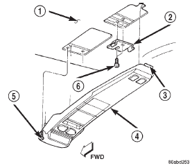
Fig. 3 Overhead Console Remove/Install
2 - REAR BRACKET
3 - REAR MOUNTING TAB
4 - OVERHEAD CONSOLE
5 - SCREW
6 - SCREWTrip computer, compass, and
thermometer display module
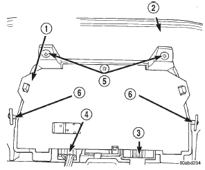
Fig. 4 Trip Computer, Compass, and Thermometer Display Module Remove/InstallPush button module
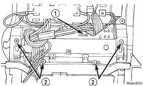
Fig. 5 Push Button Module Remove/Install
2 - MOUNTING SCREWSReading and courtesy lamp bulb
Garage door opener storage bin
door
Sunglasses storage bin
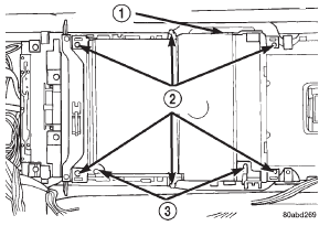
Fig. 6 Sunglasses Storage Bin Module Remove/Install
2 - MOUNTING SCREWS
3 - WIRE HARNESS RETAINERSAmbient temperature sensor
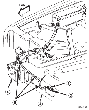
Fig. 7 Ambient Temperature Sensor Remove/Install
2 - SCREW
3 - SENSOR
4 - RADIATOR SUPPORT CROSSMEMBER
5 - CLIPS
6 - HORN
Other materials:
Exhaust manifold. Cylinder head cover. Rocker arms and push rods
Exhaust manifold
REMOVAL
(1) Disconnect the battery negative cable.
(2) Raise the vehicle.
(3) Disconnect the exhaust pipe from the engine
exhaust manifold.
(4) Lower the vehicle.
(5) Remove intake manifold (refer to procedure in
this section)
(6) Remove fasteners 2 through 5 and rem ...


