Jeep Cherokee (XJ): Removal and installation
WARNING: IF TORCHES ARE USED WHEN WORKING
ON THE EXHAUST SYSTEM, DO NOT ALLOW
THE FLAME NEAR THE FUEL LINES. CAUTION: When servicing exhaust system components,
disconnect the oxygen sensor connector.
Allowing the exhaust system to hang by the oxygen
sensor harness will damage the wiring and/or sensor. REMOVAL (1) Raise and support the vehicle.
(2) Saturate the bolts and nuts with Mopart Rust
Penetrant (Fig. 7) (Fig. 8). Allow 5 minutes for penetration.
1 - NUT (3) Disconnect the oxygen sensor connector(s).
(4) Disconnect the exhaust pipe from the engine
exhaust manifold. Discard the seal (4.0L engine,
only).
(5) Support the transmission and remove the rear
crossmember.
(6) Remove the clamp nuts and clamp. To remove
the exhaust pipe from the catalytic converter, apply
heat until the metal becomes cherry red. Disconnect
the exhaust pipe from the catalytic converter.
Remove the exhaust pipe.
1 - NUT INSTALLATION (1) Assemble exhaust pipe to manifold and catalytic
converter loosely to permit proper alignment of
all parts.
(2) Use a new clamp and tighten the nuts to 61
N·m (45 ft. lbs.) torque.
(3) Connect the exhaust pipe to the engine exhaust
manifold (Fig. 7) (Fig. 8). Install a new seal between
the exhaust manifold and the exhaust pipe (4.0L
engine only). Tighten the nuts to 31 N·m (23 ft. lbs.)
torque.
(4) Install the rear crossmember. Install and
tighten the four (4) crossmember to rear mount nuts
to 22 N·m (16 ft. lbs.) Install and tighten the crossmember
to sill bolts to 42 N·m (31 ft. lbs.) torque.
Remove the support from the transmission.
(5) Carefully coat the threads on the oxygen sensor(
s) with anti-seize compound. Install the sensor
and tighten the nut to 27 N·m (20 ft. lbs.) torque.
(6) Lower the vehicle.
(7) Start the engine and inspect for exhaust leaks
and exhaust system contact with the body panels.
Adjust the alignment, if needed. WARNING: IF TORCHES ARE USED WHEN WORKING
ON THE EXHAUST SYSTEM, DO NOT ALLOW
THE FLAME NEAR THE FUEL LINES.
CAUTION: When servicing exhaust system components,
disconnect the oxygen sensor connector.
Allowing the exhaust system to hang by the oxygen
sensor harness will damage the wiring and/or sensor. REMOVAL (1) Raise and support the vehicle.
(2) Remove the clamps from the catalytic converter
and muffler connection (Fig. 9).
(3) Disconnect and remove the oxygen sensor from
the catalytic converter.
(4) Heat the catalytic converter and muffler connection
with an oxyacetylene torch until the metal
becomes cherry red.
(5) While the metal is still cherry red, twist the
muffler assembly back and forth to separate it from
the catalytic converter.
(6) Disconnect the exhaust pipe from the catalytic
converter (Fig. 9). If needed, heat up the pipes to separate. INSTALLATION (1) Connect the catalytic converter to the exhaust
pipe and the muffler/tailpipe assy. (Fig. 9). Use a new
clamp and tighten the nuts to 61 N·m (45 ft. lbs.)
torque.
(2) Install the muffler onto the catalytic converter
until the alignment tab is inserted into the alignment
slot.
(3) Install a new clamp at the muffler and catalytic
converter connection (Fig. 9). Tighten the clamp
nut to 61 N·m (45 ft. lbs.) torque.
(4) Coat the oxygen sensor with anti-seize compound.
Install the sensor and tighten the nut to 27
N·m (20 ft. lbs.) torque.
(5) Lower the vehicle.
(6) Start the engine and inspect for exhaust leaks
and exhaust system contact with the body panels.
Adjust the alignment, if needed. All original equipment exhaust systems are manufactured
with the exhaust tailpipe welded to the muffler.
Service replacement mufflers and exhaust
tailpipes are either clamped together or welded
together.
1 - EXHAUST CLAMP ASSEMBLY WARNING: IF TORCHES ARE USED WHEN WORKING
ON THE EXHAUST SYSTEM, DO NOT ALLOW
THE FLAME NEAR THE FUEL LINE.
CAUTION: When servicing exhaust system components,
disconnect the oxygen sensor connector.
Allowing the exhaust system to hang by the oxygen
sensor harness will damage the wiring and/or sensor. REMOVAL (1) Raise and support the vehicle.
(2) Disconnect front tailpipe hanger from the insulator
(Fig. 10).
(3) Remove the front exhaust clamp from the catalytic
converter and muffler connection (Fig. 11).
(4) Heat the catalytic converter-to-muffler connection
with an oxyacetylene torch until the metal
becomes cherry red.
(5) While the metal is still cherry red, remove the
exhaust muffler/tailpipe assembly from the catalytic
converter.
(6) Slide the muffler/tailpipe assy. rearward and
out of the rear exhaust tailpipe mounting bracket
(Fig. 11).
1 - MUFFLER (7) Remove the muffler from the exhaust tailpipe: INSTALLATION (1) Install the muffler onto the catalytic converter.
Install the clamp and tighten the nut finger tight.
(2) Install the exhaust tailpipe into the rear of the
muffler.
(3) Install the exhaust tailpipe/muffler assembly
on the rear exhaust tailpipe mounting bracket. Make
sure that the exhaust tailpipe has sufficient clearance
from the floor pan.
(4) Install front tailpipe hanger into the insulator
(Fig. 10).
(5) Align the muffler and tighten the nuts on the
muffler-to-catalytic converter clamp to 61 N·m (45 ft.
lbs.) torque (Fig. 11).
(6) Align the tailpipe and install a new clamp at
the muffler to tailpipe connection.
(7) Tighten the muffler to tailpipe clamp to 61 N·m
(45 ft. lbs.)
(8) Lower the vehicle.
1 - MUFFLER AND TAIL PIPE HANGER (9) Start the engine and inspect for exhaust leaks
and exhaust system contact with the body panels.
Adjust the alignment, if needed. REMOVAL (1) Raise and support the vehicle.
(2) Remove the screws and/or nuts holding the
heat shields to the frame and/or floor pan (Fig. 12).
1 - BOLTS (3) When removing muffler heat shield, the muffler
front support bracket must be removed first.
(4) Slide the shields out around the exhaust system. INSTALLATION (1) Position the heat shields to the floor pan or the
frame and install the screws and/or nuts.
(2) Tighten the nuts and/or screws to 45 N·m (33
ft. lbs.) (Fig. 12).
(3) Lower the vehicle.Exhaust pipe
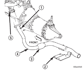
Fig. 7 Exhaust Pipe Removal-2.5L
2 - TRANSMISSION SUPPORT
3 - MINI CATALYTIC CONVERTER
4 - EXHAUST PIPE
5 - EXHAUST MANIFOLD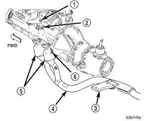
Fig. 8 Exhaust Pipe Removal-4.0L
2 - EXHAUST MANIFOLD
3 - TRANSMISSION SUPPORT
4 - EXHAUST PIPE
5 - MINI CATALYTIC CONVERTER
6 - BOLTCatalytic converter
Muffler and tailpipe
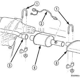
Fig. 9 Catalytic Converter to Muffler and Exhaust Pipe Connection
2 - OXYGEN SENSOR
3 - MUFFLER
4 - CATALYTIC CONVERTER
5 - EXHAUST PIPE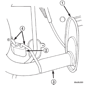
Fig. 10 Front Exhaust Tailpipe Hanger
2 - INSULATOR
3 - TAILPIPE
4 - FRONT TAILPIPE HANGER
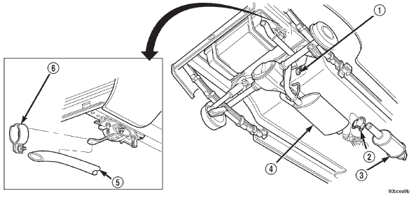
Fig. 11 Muffler/Tailpipe Removal and Installation
2 - CLAMP
3 - CATALYTIC CONVERTER
4 - MUFFLER AND TAIL PIPE ASSEMBLY
5 - TAIL PIPE
6 - TAIL PIPE HANGER CLAMPHeat shields
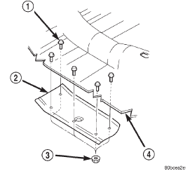
Fig. 12 Heat Shield Removal/Installation
2 - MUFFLER HEAT SHIEL
3 - NUTS
4 - FLOOR PAN


Other materials:
Lights. Doors & Locks. Engine Off Options
Lights
After pressing the "Lights" button on the touchscreen the
following settings will be available.
Headlights Off Delay
When this feature is selected, it allows the adjustment of
the amount of time the headlights remain on after the
engine is shut off. To change the Headlights Off Dela ...