Jeep Cherokee (XJ): Removal and installation
REMOVAL 2.5L ENGINE (1) Disconnect and isolate the battery negative
cable.
(2) Raise and support the vehicle.
(3) While supporting the starter motor with one
hand, use the other hand to remove the two screws
that secure the starter motor to the engine block
(Fig. 14).
(4) Lower the starter motor from the engine block
far enough to access and remove the nut that secures
the battery positive cable eyelet terminal to the
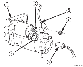
starter solenoid B(+) terminal stud (Fig. 15). Always
support the starter motor during this process. Do not
let the starter motor hang from the wire harness.
(5) Remove the battery positive cable eyelet terminal
from the starter solenoid B(+) terminal stud.
Always support the starter motor during this process.
Do not let the starter motor hang from the wire harness.
1 - STARTER MOTOR
1 - STARTER MOTOR (6) Disconnect the solenoid terminal wire harness
connector from the connector receptacle on the
starter solenoid. Always support the starter motor
during this process. Do not let the starter motor
hang from the wire harness.
(7) Remove the starter motor and any starter
motor shims (if used) from the engine block. 4.0L ENGINE (1) Disconnect and isolate the battery negative
cable.
(2) Raise and support the vehicle.
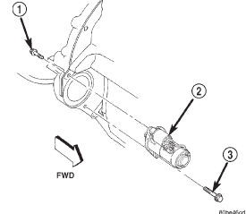
(3) Remove the lower screw (forward facing) that
secures the starter motor to the manual transmission
clutch housing or the automatic transmission torque
converter housing (Fig. 16).
1 - SCREW (4) While supporting the starter motor with one
hand, use the other hand to remove the upper screw
(rearward facing) that secures the starter motor to
the manual transmission clutch housing or the automatic
transmission torque converter housing.
(5) Lower the starter motor from the front of the
manual transmission clutch housing or automatic
transmission torque converter housing far enough to
access and remove the nut that secures the battery
positive cable eyelet terminal to the starter solenoid
B(+) terminal stud (Fig. 15). Always support the
starter motor during this process. Do not let the
starter motor hang from the wire harness.
(6) Remove the battery positive cable eyelet terminal
from the solenoid B(+) terminal stud. Always
support the starter motor during this process. Do not
let the starter motor hang from the wire harness.
(7) Disconnect the solenoid terminal wire harness
connector from the connector receptacle on the starter solenoid. Always support
the starter motor
during this process. Do not let the starter motor
hang from the wire harness.
(8) Remove the starter motor from the manual
transmission clutch housing or automatic transmission
torque converter housing. INSTALLATION 2.5L ENGINE (1) Position the starter motor to the engine block.
(2) Reconnect the solenoid terminal wire harness
connector to the connector receptacle on the starter
solenoid. Always support the starter motor during
this process. Do not let the starter motor hang from
the wire harness.
(3) Install the battery positive cable eyelet terminal
onto the starter solenoid B(+) terminal stud.
Always support the starter motor during this process.
Do not let the starter motor hang from the wire harness.
(4) Install and tighten the nut that secures the
battery positive cable eyelet terminal to the starter
solenoid B(+) terminal stud. Tighten the nut to 11.3
N·m (100 in. lbs.). Always support the starter motor
during this process. Do not let the starter motor
hang from the wire harness.
(5) Position the starter motor and any starter
motor shims that were removed during the starter
motor removal procedure to the engine block. Loosely
install the two starter motor mounting screws to
secure the starter motor and shims to the engine
block.
NOTE: Shim thickness available is 0.381 mm (0.015
in.). Refer to Starter Motor Noise - 2.5L Engine in
the index of this service manual for the location of
the proper starter motor noise diagnosis and testing
procedures.
(6) Tighten the two screws that secure the starter
motor and shims to the engine block. Tighten the
screws to 44.7 N·m (33 ft. lbs.).
(7) Lower the vehicle.
(8) Reconnect the battery negative cable. 4.0L ENGINE (1) Position the starter motor to the manual transmission
clutch housing or automatic transmission
torque converter housing.
(2) Reconnect the solenoid terminal wire harness
connector to the connector receptacle on the starter
solenoid. Always support the starter motor during
this process. Do not let the starter motor hang from
the wire harness.
(3) Install the battery positive cable eyelet terminal
onto the starter solenoid B(+) terminal stud.
Always support the starter motor during this process.
Do not let the starter motor hang from the wire harness.
(4) Install and tighten the nut that secures the
battery positive cable eyelet terminal to the starter
solenoid B(+) terminal stud. Tighten the nut to 11.3
N·m (100 in. lbs.). Always support the starter motor
during this process. Do not let the starter motor
hang from the wire harness.
(5) Position the starter motor to the manual transmission
clutch housing or automatic transmission
torque converter housing. Loosely install the two
starter motor mounting screws to secure the starter
motor to the manual transmission clutch housing or
automatic transmission torque converter housing.
(6) Tighten the lower (forward facing) screw that
secures the starter motor to the manual transmission
clutch housing or automatic transmission torque converter
housing. Tighten the screw to 40.7 N·m (30 ft.
lbs.).
(7) Tighten the upper (rearward facing) screw that
secures the starter motor to the manual transmission
clutch housing or automatic transmission torque converter
housing. Tighten the screw to 47.5 N·m (35 ft.
lbs.).
(8) Lower the vehicle.
(9) Reconnect the battery negative cable. REMOVAL (1) Disconnect and isolate the battery negative
cable.
(2) Remove the cover from the Power Distribution
Center (PDC) (Fig. 17).
(3) See the fuse and relay layout label affixed to
the underside of the PDC cover for starter relay identification
and location.
(4) Remove the starter relay from the PDC. INSTALLATION (1) See the fuse and relay layout label affixed to
the underside of the PDC cover for the proper starter
relay location.
(2) Position the starter relay in the proper receptacle
in the PDC.
(3) Align the starter relay terminals with the terminal
cavities in the PDC receptacle.
(4) Push down firmly on the starter relay until the
terminals are fully seated in the terminal cavities in
the PDC receptacle.
(5) Install the cover onto the PDC.
(6) Reconnect the battery negative cable.
1 - RIGHT FENDERStarter motor

Fig. 14 Starter Motor Remove/Install - 2.5L Engine
2 - SCREW (2)
3 - SHIM
Fig. 15 Starter Connections Remove/Install - Typical
2 - SOLENOID B(+) TERMINAL STUD
3 - BATTERY POSITIVE CABLE EYELET TERMINAL
4 - NUT
5 - SOLENOID TERMINAL WIRE HARNESS CONNECTOR
6 - SOLENOID TERMINAL CONNECTOR RECEPTACLE
Fig. 16 Starter Motor Remove/Install - 4.0L Engine
2 - STARTER MOTOR
3 - SCREWStarter relay

Fig. 17 Power Distribution Center
2 - BATTERY
3 - POWER DISTRIBUTION CENTER
 Starter motor noise - 2.5L engine. Starter motor. Starter relay
Other materials:
Vehicle security alarm
The Vehicle Security Alarm monitors the vehicle doors
for unauthorized entry and the Keyless Enter-N-Go
Start/Stop button for unauthorized operation. While the
Vehicle Security Alarm is armed, interior switches for
door locks and liftgate release are disabled.
If something triggers the alarm, ...

