Jeep Cherokee (XJ): Specifications. Special tools
Axle Type . . . . . . . . . . . . . . . . . . . . . . . . . . Hypoid Axle Type . . . . . . . . . . . . . . . . . . . . . . . . . . Hypoid DESCRIPTION TORQUE Fill Hole Plug . . . . . . . . . . . . . . 34 N·m (25 ft. lbs.) 181 and 186 FBI AXLE
Specifications
181 FBI axle
Lubricant-Std. . . . . SAE Thermally Stable 80W-90
Lubricant-Heavy Duty . . . SAE 75W-140 Synthetic
Lube Capacity . . . . . . . . . . . . . . . 1.48 L (3.13 pts.)
Axle Ratio . . . . . . . . . . . . . . . . 3.07, 3.55, 3.73, 4.10
Differential Side Gear Clearance . . . 0.12-0.20 mm
(0.005-0.008 in.)
Ring Gear Diameter . . . . . . . . . 18.09 cm (7.125 in.)
Backlash . . . . . . . . . . . 0-0.15 mm (0.005-0.008 in.)
Pinion Std. Depth . . . . . . . . . . . 92.1 mm (3.625 in.)
Pinion Bearing Rotating Torque . . . . . . . . . . . . . . .
Original Bearings . . . . . . . 1-2 N·m (10-20 in. lbs.)
New Bearings . . . . . . . . . 1.5-4 N·m (15-35 in. lbs.)186 FBI axle
Lubricant-Std. . . . . SAE Thermally Stable 80W-90
Lubricant-Heavy Duty . . . SAE 75W-140 Synthetic
Lube Capacity . . . . . . . . . . . . . . . . 1.18 L (2.5 pts.)
Axle Ratio . . . . . . . . . . . . . . . . 3.07, 3.55, 3.73, 4.10
Differential Side Gear Clearance . . . 0.12-0.20 mm
(0.005-0.008 in.)
Ring Gear Diameter . . . . . . . . . 18.59 cm (7.33 in.)
Backlash . . . . . . . . . . . 0-0.15 mm (0.005-0.008 in.)
Pinion Std. Depth . . . . . . . . . . . 92.1 mm (3.625 in.)
Pinion Bearing Rotating Torque . . . . . . . . . . . . . . .
Original Bearings . . . . . . . 1-2 N·m (10-20 in. lbs.)
New Bearings . . . . . . . . . 1.5-4 N·m (15-35 in. lbs.)Torque
Diff. Cover Bolt . . . . . . . . . . . . . 41 N·m (30 ft. lbs.)
Bearing Cap Bolt . . . . . . . . . . . . 61 N·m (45 ft. lbs.)
Ring Gear Bolt . . . . . . . 95-122 N·m (70-90 ft. lbs.)
Axle Nut . . . . . . . . . . . . . . . . 237 N·m (175 ft. lbs.)
Hub Brg. Bolt . . . . . . . . . . . . . 102 N·m (75 ft. lbs.)
Lower Ball Stud . . . . . . . . . . . 108 N·m (80 ft. lbs.)
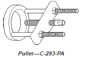
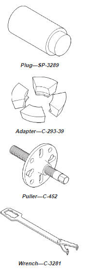
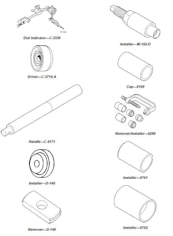
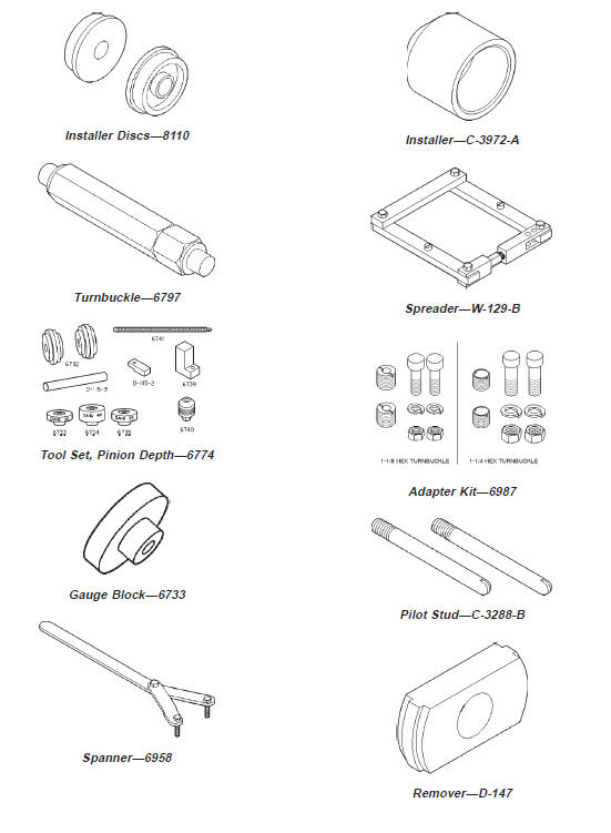
Upper Ball Stud . . . . . . . . . . . 101 N·m (75 ft. lbs.)Special tools


Other materials:
Electric cooling fan. Radiator cap-to-filler neck
seal-pressure relief check. Radiator cap-pressure testing
Electric cooling fan
ELECTRIC COOLING FAN AND RELAY DIAGNOSIS
NOTE: Refer to Electrical Group 8W for electric
cooling fan and relay circuit schematic.
The powertrain control module (PCM) will enter a
diagnostic trouble code (DTC) in memory if it detects
a problem in the auxiliary cooling fan ...