Jeep Cherokee (XJ): Transmission
CAUTION: The transmission and torque converter must be removed as an assembly to avoid component damage. The converter drive plate, pump bushing, or oil seal can be damaged if the converter is left attached to the driveplate during removal.
REMOVAL
(1) Disconnect battery negative cable.
(2) Disconnect and lower or remove necessary exhaust components.
(3) Remove engine-to-transmission bending braces.
(4) Disconnect fluid cooler lines at transmission.
(5) Remove starter motor.
(6) Disconnect and remove crankshaft position sensor (Fig. 67). Retain sensor attaching bolts.
CAUTION: The crankshaft position sensor can be damaged during transmission removal (or installation) if the sensor is left in place. To avoid damage, remove the sensor before removing the transmission.
Fig. 67 Crankshaft Position Sensor-2.5L Engine
1 - EXHAUST DOWN PIPE
2 - TRANSMISSION HOUSING
3 - CRANKSHAFT POSITION SENSOR
(7) Remove torque converter access cover.
(8) If transmission is being removed for overhaul, remove transmission oil pan, drain fluid and reinstall pan.
(9) Remove skid plate for access.
(10) Remove the fill tube bracket bolts and pull tube out of transmission. Retain fill tube seal. On 4 x 4 models, it will also be necessary to remove bolt attaching transfer case vent tube to converter housing.
(11) Rotate crankshaft in clockwise direction until converter bolts are accessible. Then remove bolts one at a time. Rotate crankshaft with socket wrench on dampener bolt.
(12) Mark propeller shaft and axle yokes for assembly alignment. Then disconnect and remove propeller shafts.
(13) Disconnect wires from park/neutral position switch and vehicle speed sensor.
(14) Disconnect gearshift cable from transmission manual valve lever.
(15) Disconnect throttle valve cable from transmission bracket and throttle valve lever.
(16) Disconnect shift rod from transfer case shift lever or remove shift lever from transfer case.
(17) Support rear of engine with safety stand or jack.
(18) Raise transmission slightly with service jack to relieve load on crossmember and supports.
(19) Remove bolts securing rear support and cushion to transmission and crossmember. Raise transmission slightly, slide exhaust hanger arm from bracket and remove rear support.
(20) Remove bolts attaching crossmember to frame and remove crossmember.
(21) Disconnect transfer case vent hose. Then disconnect vacuum switch harness.
(22) Remove transfer case.
(23) Remove all converter housing bolts.
(24) Carefully work transmission and torque converter assembly rearward off engine block dowels.
(25) Hold torque converter in place during transmission removal.
(26) Lower transmission and remove assembly from under the vehicle.
(27) To remove torque converter, carefully slide torque converter out of the transmission.
INSTALLATION
(1) Check torque converter hub and hub drive notches for sharp edges burrs, scratches, or nicks.
Polish the hub and notches with 320/400 grit paper and crocus cloth if necessary. The hub must be smooth to avoid damaging pump seal at installation.
(2) Lubricate converter drive hub and oil pump seal lip with transmission fluid.
(3) Align converter and oil pump.
(4) Carefully insert converter in oil pump. Then rotate converter back and forth until fully seated in pump gears.
(5) Check converter seating with steel scale and straightedge (Fig. 68). Surface of converter lugs should be 1/2 in. to rear of straightedge when converter is fully seated.
(6) Temporarily secure converter with C-clamp.
(7) Lubricate the pocket in the rear of the crankshaft, in which the converter pilot hub rides, with a light coating of Mopart High-Temp Grease.
(8) Position transmission on jack and secure it with safety chains.
(9) Check condition of converter driveplate.
Replace the plate if cracked, distorted or damaged.
Also be sure transmission dowel pins are seated in engine block and protrude far enough to hold transmission in alignment.
(10) Raise transmission and align converter with drive plate and converter housing with engine block.
(11) Move transmission forward. Then raise, lower or tilt transmission to align converter housing with engine block dowels.
Fig. 68 Typical Method Of Checking Converter Seating
1 - SCALE
2 - STRAIGHTEDGE
(12) Carefully work transmission forward and over engine block dowels until converter hub is seated in crankshaft.
(13) Install and tighten bolts that attach transmission converter housing to engine block (Fig. 69).
CAUTION: Be sure the converter housing is fully seated on the engine block dowels before tightening any bolts.
(14) Install torque converter attaching bolts.
Tighten bolts to following torque.
- 54 N·m (40 ft. lbs.) with 9.5 in. 3-lug converter
- 74 N·m (55 ft. lbs.) with 9.5 in. 4-lug converter
- 74 N·m (55 ft. lbs.) with 10.0 in. 4-lug converter
- 31 N·m (270 in. lbs.) with 10.75 in. 4-lug converter
(15) Install crankshaft position sensor.
(16) Install transmission fill tube and seal. Install new fill tube seal in transmission before installation.
(17) Connect transmission cooler lines to transmission.
(18) Install transfer case onto transmission.
(19) Install rear crossmember and attach transmission rear support to crossmember.
(20) Remove engine support fixture.
(21) Remove transmission jack.
(22) Connect vehicle speed sensor wires.
(23) Connect wires to park/neutral position switch.
(24) Install crankshaft position sensor.
(25) Install converter housing access cover.
(26) Install exhaust pipes and support brackets, if removed.
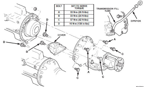
Fig. 69 Transmission Attachment
(27) Install starter motor and cooler line bracket.
(28) Install new plastic retainer grommet on any shift linkage rod or lever that was disconnected.
Grommets should not be reused. Use pry tool to remove rod from grommet and cut away old grommet.
Use pliers to snap new grommet into lever and to snap rod into grommet at assembly.
(29) Connect gearshift and linkage and throttle cable.
(30) Connect transfer case shift linkage.
(31) Adjust gearshift linkage and throttle valve cable if necessary.
(32) Align and connect propeller shaft(s).
(33) Install skid plate, rear cushion and bracket, if removed.
(34) Fill transfer case to bottom edge of fill plug hole.
(35) Lower vehicle and fill transmission to correct level with Mopart ATF Plus 3, type 7176 fluid.

 Torque converter. Yoke seal replacement. Extension housing bushing
Other materials:
Differential side bearings. Ring gear. Pinion gear
Differential side bearings
REMOVAL
(1) Remove differential from axle housing.
(2) Remove the bearings from the differential case
with Puller/Press C-293-PA, C-293-39 Blocks, and
Plug SP-3289 (Fig. 30).
Fig. 30 Differential Bearing Removal
1 - SPECIAL TOOL C-293-39
2 - BEARING
3 - DIFFE ...