Jeep Cherokee (XJ): 186 FBI pinion gear depth
GENERAL INFORMATION
Ring gear and pinion are supplied as matched sets only. The identifying numbers for the ring gear and pinion are etched into the face of each gear (Fig. 77).
A plus (+) number, minus (-) number or zero (0) is etched into the face of the pinion gear head. This number is the amount (in thousandths of an inch) the depth varies from the standard depth setting of a pinion etched with a (0). The standard setting from the center line of the ring gear to the back face of the pinion is 92.08 mm (3.625 in.). The standard depth provides the best gear tooth contact pattern. Refer to Backlash and Contact Pattern Analysis paragraph in this section for additional information.
Fig. 76 Pinion Gear Depth Measurement-Typical
1 - ARBOR
2 - SCOOTER BLOCK
3 - DIAL INDICATOR
Fig. 77 Pinion Gear ID Numbers
1 - PRODUCTION NUMBERS
2 - DRIVE PINION GEAR DEPTH VARIANCE
3 - GEAR MATCHING NUMBER (SAME AS RING GEAR
NUMBER)
Compensation for pinion depth variance is achieved with a select shim/oil slinger. The shim/oil slinger is placed between the rear pinion bearing and the pinion gear head (Fig. 78).
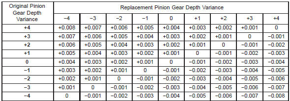
If a new gear set is being installed, note the depth variance etched into both the original and replacement pinion. Add or subtract the thickness of the original depth shims to compensate for the difference in the depth variances. Refer to the Depth Variance chart
Fig. 78 Shim Locations
1 - PINION GEAR DEPTH SHIM/OIL BAFFLE
2 - DIFFERENTIAL BEARING SHIM
Note where Old and New Pinion Marking columns intersect. Intersecting figure represents plus or minus the amount needed.
Note the etched number on the face of the drive pinion (-1, -2, 0, +1, +2, etc.). The numbers represent thousands of an inch deviation from the standard.
If the number is negative, add that value to the required thickness of the depth shim/oil slinger. If the number is positive, subtract that value from the thickness of the depth shim/oil slinger. If the number is 0 no change is necessary.
PINION DEPTH MEASUREMENT AND ADJUSTMENT
Measurements are taken with pinion bearing cups and pinion bearings installed in the axle housing.
Take measurements with Pinion Gauge Set 6774 and Dial Indicator C-3339 (Fig. 79).
Fig. 79 Pinion Gear Depth Gauge Tools-Typical
1 - DIAL INDICATOR
2 - ARBOR
3 - PINION HEIGHT BLOCK
4 - CONE
5 - SCREW
6 - PINION BLOCK
7 - SCOOTER BLOCK
8 - ARBOR DISC
PINION GEAR DEPTH VARIANCE
(1) Assemble Pinion Height Block 6739, Pinion Block 6733, and rear pinion bearing onto Screw 6741 (Fig. 79).
(2) Insert assembled height gauge components, rear bearing and screw into axle housing through pinion bearing cups (Fig. 80).
(3) Install front pinion bearing and Cone-nut 6740 hand tight (Fig. 79).
Fig. 80 Pinion Height Block-Typical
1 - PINION BLOCK
2 - PINION HEIGHT BLOCK
(4) Place Arbor Disc 6732 on Arbor D-115-3 in position in axle housing side bearing cradles (Fig. 81).
Install differential bearing caps on Arbor Discs and tighten cap bolts to 41 N·m (30 ft. lbs.).
NOTE: Arbor Discs 6732 has different step diameters to fit other axles. Choose proper step for axle being serviced.
(5) Assemble Dial Indicator C-3339 into Scooter Block D-115-2 and secure set screw.
(6) Place Scooter Block/Dial Indicator in position in axle housing so dial probe and scooter block are flush against the rearward surface of the pinion height block (Fig. 79). Hold scooter block in place and zero the dial indicator face to the pointer. Tighten dial indicator face lock screw.
(7) With scooter block still in position against the pinion height block, slowly slide the dial indicator probe over the edge of the pinion height block.
(8) Slide the dial indicator probe across the gap between the pinion height block and the arbor bar with the scooter block against the pinion height block (Fig. 82). When the dial probe contacts the arbor bar, the dial pointer will turn clockwise. Bring dial pointer back to zero against the arbor bar, do not turn dial face. Continue moving the dial probe to the crest of the arbor bar and record the highest reading.
Fig. 81 Gauge Tools In Housing-Typical
1 - ARBOR DISC
2 - PINION BLOCK
3 - ARBOR
4 - PINION HEIGHT BLOCK
If the dial indicator can not achieve the zero reading, the rear bearing cup or the pinion depth gauge set is not installed correctly.
(9) Select a shim/oil slinger equal to the dial indicator reading plus the drive pinion depth variance number etched in the face of the pinion (Fig. 77). For example, if the depth variance is -2, add +0.002 in.
to the dial indicator reading.
Fig. 82 Pinion Gear Depth Measurement-Typical
1 - ARBOR
2 - SCOOTER BLOCK
3 - DIAL INDICATOR

 181 FBI differential bearing preload
and gear backlash
181 FBI differential bearing preload
and gear backlash
Other materials:
Inside Day/Night Mirror. Assist And 9-1-1 Rearview Mirror. Outside Mirrors
Inside Day/Night Mirror - If Equipped
The mirror head can be adjusted up, down, left, and right
for various drivers. The mirror should be adjusted to
center on the view through the rear window.
Headlight glare from vehicles behind you can be reduced
by moving the small control under the mirror ...