Jeep Cherokee (XJ): A/C performance
The air conditioning system is designed to provide the passenger compartment with low temperature and low humidity air. The evaporator, located in the heater-A/C housing on the dash panel below the instrument panel, is cooled to temperatures near the freezing point. As warm damp air passes through the cooled evaporator, the air transfers its heat to the refrigerant in the evaporator and the moisture in the air condenses on the evaporator fins. During periods of high heat and humidity, an air conditioning system will be more effective in the Recirculation Mode.
With the system in the Recirculation Mode, only air from the passenger compartment passes through the evaporator. As the passenger compartment air dehumidifies, the air conditioning system performance levels improve.
Humidity has an important bearing on the temperature of the air delivered to the interior of the vehicle.
It is important to understand the effect that humidity has on the performance of the air conditioning system. When humidity is high, the evaporator has to perform a double duty. It must lower the air temperature, and it must lower the temperature of the moisture in the air that condenses on the evaporator fins. Condensing the moisture in the air transfers heat energy into the evaporator fins and tubing.
This reduces the amount of heat the evaporator can absorb from the air. High humidity greatly reduces the ability of the evaporator to lower the temperature of the air.
However, evaporator capacity used to reduce the amount of moisture in the air is not wasted. Wringing some of the moisture out of the air entering the vehicle adds to the comfort of the passengers.
Although, an owner may expect too much from their air conditioning system on humid days. A performance test is the best way to determine whether the system is performing up to standard. This test also provides valuable clues as to the possible cause of trouble with the air conditioning system.
Review the Service Warnings and Precautions in the front of this group before performing this procedure.
The air temperature in the test room and in the vehicle must be a minimum of 21 C (70 F) for this test.
(1) Connect a tachometer and a manifold gauge set.
(2) Set the heater-A/C mode control switch knob in the Recirculation Mode position, the temperature control knob in the full cool position, and the blower motor switch knob in the highest speed position.
(3) Start the engine and hold the idle at 1,000 rpm with the compressor clutch engaged.
(4) The engine should be at operating temperature.
The doors and windows must be open.
(5) Insert a thermometer in the driver side center A/C (panel) outlet. Operate the engine for five minutes.
(6) The compressor clutch may cycle, depending upon the ambient temperature and humidity. If the clutch cycles, unplug the low pressure cycling clutch switch wire harness connector from the switch located on the accumulator (Fig. 6). Place a jumper wire across the terminals of the low pressure cycling clutch switch wire harness connector.
Fig. 6 Low Pressure Cycling Clutch Switch - Typical
1 - LOW PRESSURE CYCLING CLUTCH SWITCH
2 - ACCUMULATOR
(7) With the compressor clutch engaged, record the discharge air temperature and the compressor discharge pressure.
(8) Compare the discharge air temperature to the Performance Temperature and Pressure chart. If the discharge air temperature is high, see Refrigerant System Leaks and Refrigerant System Charge in this group.
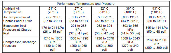
(9) Compare the compressor discharge pressure to the Performance Temperature and Pressure chart. If the compressor discharge pressure is high, see the Pressure Diagnosis chart.
|
Pressure Diagnosis |
||
|
Condition |
Possible Causes |
Correction |
| Rapid compressor clutch cycling (ten or more cycles per minute). |
|
|
| Equal pressures, but the compressor clutch does not engage. |
|
|
| Normal pressures, but A/C Performance Test air temperatures at center panel outlet are too high. |
|
|
| The low side pressure is normal or slightly low, and the high side pressure is too low. |
|
|
| The low side pressure is normal or slightly high, and the high side pressure is too high. |
|
|
| The low side pressure is too high, and the high side pressure is too low. |
|
|
| The low side pressure is too low, and the high side pressure is too high. |
|
|

 Blower motor. Blower motor relay. Blower motor resistor
Other materials:
High pressure cut-off switch. High pressure relief valve. Low pressure cycling clutch switch
High pressure cut-off switch
DESCRIPTION
The high pressure cut-off switch is located on the
discharge line between the compressor and the condenser
inlet. The switch is screwed onto a fitting that
contains a Schrader-type valve, which allows the
switch to be serviced without discharging the ref ...