Jeep Cherokee (XJ): Blower motor. Blower motor relay. Blower motor resistor
WARNING: ON VEHICLES EQUIPPED WITH AIRBAGS,
REFER TO GROUP 8M - PASSIVE RESTRAINT
SYSTEMS BEFORE ATTEMPTING ANY STEERING
WHEEL, STEERING COLUMN, OR INSTRUMENT
PANEL COMPONENT DIAGNOSIS OR SERVICE. FAILURE
TO TAKE THE PROPER PRECAUTIONS COULD
RESULT IN ACCIDENTAL AIRBAG DEPLOYMENT
AND POSSIBLE PERSONAL INJURY.
For circuit descriptions and diagrams, refer to
8W-42 - Air Conditioning/Heater in Group 8W - Wiring
Diagrams. Possible causes of an inoperative
blower motor include: Possible causes of the blower motor not operating
in all speeds include: VIBRATION Possible causes of blower motor vibration include: NOISE To verify that the blower is the source of the noise,
unplug the blower motor wire harness connector and
operate the heater-A/C system. If the noise goes
away, possible causes include: WARNING: ON VEHICLES EQUIPPED WITH AIRBAGS,
REFER TO GROUP 8M - PASSIVE
RESTRAINT SYSTEMS BEFORE ATTEMPTING ANY
STEERING WHEEL, STEERING COLUMN, OR
INSTRUMENT PANEL COMPONENT DIAGNOSIS OR
SERVICE. FAILURE TO TAKE THE PROPER PRECAUTIONS
COULD RESULT IN ACCIDENTAL AIRBAG
DEPLOYMENT AND POSSIBLE PERSONAL
INJURY. RELAY TEST The blower motor relay (Fig. 7) is located in a wire
harness connector that is secured to the heater-A/C
housing behind the glove box on the passenger side
of the vehicle, next to the heater-A/C wire harness
connector in the passenger compartment. Remove the
relay from its connector to perform the following
tests:
(1) A relay in the de-energized position should
have continuity between terminals 87A and 30, and
no continuity between terminals 87 and 30. If OK, go
to Step 2. If not OK, replace the faulty relay.
(2) Resistance between terminals 85 and 86 (electromagnet)
should be 75 6 5 ohms. If OK, go to Step
3. If not OK, replace the faulty relay.
(3) Connect a battery to terminals 85 and 86.
There should now be continuity between terminals
30 and 87, and no continuity between terminals 87A
and 30. If OK, see the Relay Circuit Test procedure
in this group. If not OK, replace the faulty relay.
RELAY CIRCUIT TEST For circuit descriptions and diagrams, refer to
8W-42 - Air Conditioning/Heater in Group 8W - Wiring
Diagrams.
(1) The relay common feed terminal cavity (30) is
connected to fused battery feed directly from a fuse
in the Power Distribution Center (PDC), and should
be hot at all times. Check for battery voltage at the
connector cavity for relay terminal 30. If OK, go to
Step 2. If not OK, repair the open circuit to the PDC
fuse as required.
(2) The relay normally closed terminal cavity (87A)
is not used for this application. Go to Step 3.
(3) The relay normally open terminal cavity (87) is
connected to the blower motor. When the relay is
energized, terminal 87 is connected to terminal 30
and provides full battery current to the blower motor
feed circuit. There should be continuity between the
connector cavity for terminal 87 and the blower
motor relay output circuit cavity of the blower motor
wire harness connector at all times. If OK, go to Step
4. If not OK, repair the open circuit to the blower
motor as required.
(4) The coil battery terminal cavity (86) is connected
to the ignition switch. When the ignition
switch is placed in the On position, fused ignition
switch output is directed from a fuse in the junction
block to the relay electromagnetic coil to energize the
relay. There should be battery voltage at the connector
cavity for relay terminal 86 with the ignition
switch in the On position. If OK, go to Step 5. If not
OK, repair the open circuit to the junction block fuse
as required.
(5) The coil ground terminal cavity (85) is connected
to ground. This terminal supplies the ground
for the relay electromagnet coil. There should be continuity
between the connector cavity for relay terminal 85 and a good ground at all
times. If not OK,
repair the open circuit as required. For circuit descriptions and diagrams, refer to
8W-42 - Air Conditioning/Heater in Group 8W - Wiring
Diagrams.
WARNING: ON VEHICLES EQUIPPED WITH AIRBAGS,
REFER TO GROUP 8M - PASSIVE
RESTRAINT SYSTEMS BEFORE ATTEMPTING ANY
STEERING WHEEL, STEERING COLUMN, OR
INSTRUMENT PANEL COMPONENT DIAGNOSIS OR
SERVICE. FAILURE TO TAKE THE PROPER PRECAUTIONS
COULD RESULT IN ACCIDENTAL AIRBAG
DEPLOYMENT AND POSSIBLE PERSONAL
INJURY.
(1) Disconnect and isolate the battery negative
cable.
(2) Remove the kick cover from the heater-A/C
housing and unplug the wire harness connector from
the blower motor resistor.
(3) Check for continuity between each of the
blower motor switch input terminals of the resistor
and the resistor output terminal. In each case there
should be continuity. If OK, repair the wire harness
circuits between the blower motor switch and the
blower motor resistor or blower motor relay as
required. If not OK, replace the faulty blower motor
resistor.Blower motor
Blower motor relay
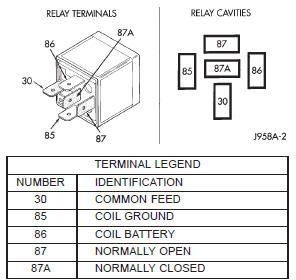
Fig. 7 Blower Motor RelayBlower motor resistor

 Blower motor switch. Compressor. Compressor clutch coil
Other materials:
Hood release cable. Hood safety latch. Safety latch striker
Hood release cable
REMOVAL
(1) Drill out bellcrank to hood rivet heads and
remove rivets (Fig. 6).
(2) Disconnect bellcrank from latch rod and hood
release cable. Remove bellcrank from hood.
(3) Disconnect hood release cable from clips on
hood.
(4) Remove left cowl side trim panel.
( ...