Jeep Cherokee (XJ): Adjustments
STEERING GEAR
CAUTION: Steering gear must be adjusted in the proper order. If adjustments are not performed in order, gear damage and improper steering response may result.
NOTE: Adjusting the steering gear in the vehicle is not recommended. Remove gear from the vehicle and drain the fluid. Then mount gear in a vise to perform adjustments.
WORM THRUST BEARING PRELOAD
(1) Mount the gear carefully into a vise.
CAUTION: Do not overtighten the vise on the gear case. This may affect the adjustment (2) Remove adjuster plug locknut (Fig. 23).
(3) Rotate the stub shaft back and forth with a 12 point socket to drain the remaining fluid.
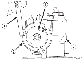
Fig. 23 Adjuster Lock Nut
1 - ADJUSTER NUT
2 - STEERING GEAR
3 - LOCK NUT
4 - PUNCH
(4) Turn the adjuster in with Spanner Wrench C-4381. Tighten the plug and thrust bearing in the housing until firmly bottomed in the housing about 34 N·m (25 ft. lbs.).
(5) Place an index mark on the housing even with one of the holes in adjuster plug (Fig. 24).
(6) Measure back (counterclockwise) 5.08 mm (0.20 in) and mark housing (Fig. 25).

Fig. 24 Alignment Marking On Housing
1 - INDEX
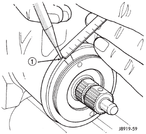
Fig. 25 Second Marking On Housing
1 - REFERENCE MARK
(7) Rotate adjustment cap back (counterclockwise) with spanner wrench until hole is aligned with the second mark (Fig. 26).
(8) Install and tighten locknut to 108 N·m (80 ft.
lbs.). Be sure adjustment cap does not turn while tightening the locknut.
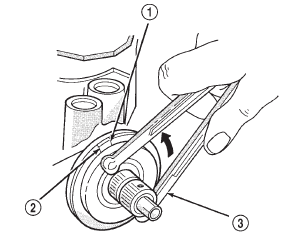
Fig. 26 Aligning To The Second Mark
1 - FIRST MARK
2 - SECOND MARK
3 - SPANNER WRENCH
OVER-CENTER
NOTE: Before performing this procedure, the worm bearing preload adjustment must be performed.
(1) Rotate the stub shaft with a 12 point socket from stop to stop and count the number of turns.
(2) Starting at either stop, turn the stub shaft back 1/2 the total number of turns. This is the center of the gear travel (Fig. 27).
(3) Place the torque wrench in the vertical position on the stub shaft. Rotate the wrench 45 degrees each side of the center and record the highest rotational torque in this range (Fig. 28). This is the Over-Center Rotating Torque.
NOTE: The stub shaft must rotate smoothly without sticking or binding.
(4) Rotate the stud shaft between 90 and 180 to the left of center and record the left off-center preload.
Repeat this to the right of center and record the right off-center preload. The average of these two recorded readings is the Preload Rotating Torque.
(5) The Over-Center Rotating Torque should be 0.40-0.70 N·m (3-7 in. lbs.) higher than the Preload Rotating Torque.
(6) If an adjustment to the Over-Center Rotating Torque is necessary, first loosen the adjuster lock nut. Then turn the pitman shaft adjuster screw back (COUNTERCLOCKWISE) until fully extended, then turn back in (CLOCKWISE) one full turn.
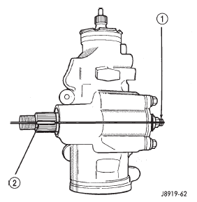
Fig. 27 Steering Gear Centered
1 - ADJUSTMENT SCREW
2 - MASTER SPLINE
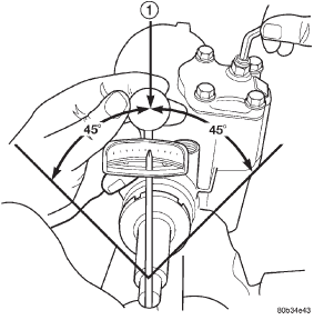
Fig. 28 Checking Over-center Rotation Torque
1 - CENTER
(7) Remeasure Over-Center Rotating Torque. If necessary turn the adjuster screw and repeat mea surement until correct Over-Center Rotating Torque is reached.
NOTE: To increase the Over-Center Rotating Torque turn the screw CLOCKWISE.
(8) Prevent the adjuster screw from turning while tightening adjuster lock nut. Tighten the adjuster lock nut to 49 N·m (36 ft. lbs.).
Other materials:
Description and operation
Power mirror
Each power mirror head contains two electric
motors, two drive mechanisms, and the mirror glass.
One motor and drive controls mirror up-and-down
movement, and the other controls right-and-left
movement.
The power mirrors in vehicles equipped with the
available heated mirror op ...


