Jeep Cherokee (XJ): Adjustments
The hood bolt holes are elongated for fore and aft
and side-to-side adjustment.
(1) If hood is low to the cowl panel, insert shims
between the hinge and hood at the rear hinge bolts.
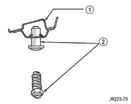
(2) Adjust the hood bumper (Fig. 95) in or out to
provide proper hood-to-fender height alignment.
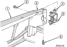
(3) Adjust the hood strikers (Fig. 96) with shims
as necessary. Tighten the screws to 22 N·m (16 ft-lbs)
torque after adjustment.
(4) Align each latch and striker so that the striker
enters latch squarely. IN AND OUT-MINOR ADJUSTMENT (1) Loosen the latch striker.
(2) Tap the latch striker inward if the door character
line is outboard of the body character line or tap
the latch striker outward if the door character line is
inboard of the body character line.
(3) Inspect alignment. If correct, tighten striker
with 28 N·m (20 ft. lbs.) torque.
1 - HOOD LATCH STRIKER REINFORCEMENT PANEL
1 - RADIATOR SUPPORT CROSSMEMBER UP AND DOWN-MINOR ADJUSTMENT (1) Loosen the latch striker.
(2) Tap the latch striker downward if the door
character line is higher than the body character line
or tap the latch striker upward if the door character
line is lower than the body character line.
(3) Inspect alignment. If correct, tighten striker
with 28 N·m (20 ft. lbs.) torque. ALIGNMENT MAJOR-ADJUSTMENT Adjustment for alignment of the door is made by
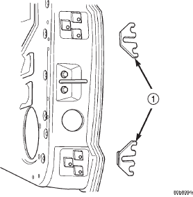
installing shims between hinge and door face (Fig.
97).
1 - ADJUSTMENT SHIMS (1) If not loosened, loosen the door hinge bolts.
(2) Add or remove shims as necessary to obtain
the best door fit.
(3) Tighten door hinge bolts to 3 N·m (2 ft-lbs)
torque after adjustment is completed.
(4) Apply general purpose sealant around the door
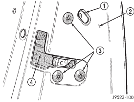
hinges/door face mating area. (1) Locate access hole (Fig. 98).
(2) Insert a 5/32-inch hex-wrench through hole and
into adjustment screw. Loosen screw.
(3) Operate outside handle button several times to
release any restriction because of mis-alignment.
(4) Tighten adjustment screw to 3 N·m (30 in-lbs)
torque.
(5) Test handle button and lock cylinder for proper
operation.
1 - ACCESS HOLE The position of liftgate can be adjusted upward or
downward by use of slots in the hinge. An inward or
outward adjustment is achieved by use of slots in the
body. If an inward or outward adjustment is needed,
use 3My Fast and Firm or equivalent on the hinge
to body mating surface as a sealant. (1) Unlatch and position seatback in cargo position.
(2) Loosen the screws attaching the strikers to the
rear wheelhouse.
(3) Position the seat back in the full upright position
and secure the latch into the strikers.
(4) From the cargo area of the vehicle, push the
rear of the seatback forward.
(5) Unlatch and position seatback in cargo position.
(6) Tighten the screws attaching the strikers to
the rear wheelhouse.
(7) Position the seat back in the full upright position
and secure the latch into the strikers.
(8) Verify latch operation.Hood
Door

Fig. 95 Hood Bumper
2 - HOOD BUMPER
Fig. 96 Hood Latch Striker
2 - SCREW
3 - RADIATOR BAFFLE
4 - SHIM
5 - HOOD LATCH STRIKER
6 - SCREW
Fig. 97 Door Adjustment ShimsDoor latch adjustment

2 - DOOR
3 - LATCH MOUNTING BOLTS
4 - LATCHLiftgate
Rear seatback
 Liftgate latch. Liftgate latch striker. Liftgate weatherstrip
Other materials:
Tire Spinning. Tread Wear Indicators. Life Of Tire
Tire Spinning
When stuck in mud, sand, snow, or ice conditions, do not
spin your vehicle's wheels above 30 mph (48 km/h) or
for longer than 30 seconds continuously without stopping.
Refer to "Freeing A Stuck Vehicle" in "What To Do In
Emergencies" for further information.
WARNING!
Fast spinn ...

