Jeep Cherokee (XJ): AW-4 automatic transmission
DESCRIPTION
The AW-4 is a 4-speed, electronically controlled automatic transmission (Fig. 1).
The running gear consists of an oil pump, planetary gear sets, clutch and brake units, hydraulic accumulators, a valve body with electrical solenoids, and a transmission control module (TCM). Cables are used to provide shift and throttle pressure control information. A park/neutral position switch permits engine starting in the Park and Neutral ranges only.
TRANSMISSION IDENTIFICATION
The transmission I. D. plate is attached to the case (Fig. 2). The plate contains the transmission serial and model numbers. Refer to the information on this plate when ordering service parts.
ELECTRONIC CONTROLS
The AW-4 is electronically controlled in 1, 2, 3 and D ranges. Controls consist of the transmission control module (TCM), valve body solenoids and various sensors.
The sensors monitor vehicle speed, throttle opening, shift lever position and brake pedal application.
TRANSMISSION GEAR RATIOS
Fourth gear is an 0.75:1 ratio overdrive range.
First, second, third and reverse gear are conventional ranges. Third gear ratio is 1:1. A separate planetary gear set provides overdrive operation in fourth gear.
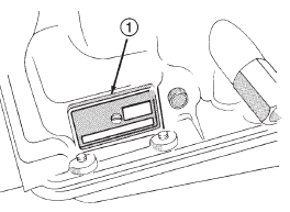
Fig. 2 Transmission Identification
1 - TRANSMISSION I. D. PLATE
OPERATION
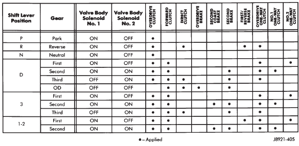
GEARTRAIN OPERATION AND APPLICATION CHARTS
Operation and application of the first through fourth and reverse gear elements are outlined in the function and application charts.
The Component Function Chart describes basic function of various geartrain elements. The Component Application Chart indicates which elements (including valve body solenoids), are applied in the various gear ranges.
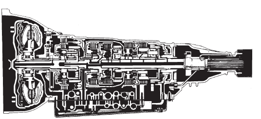
Fig. 1 AW-4 Automatic Transmission
COMPONENT FUNCTION CHART
|
COMPONENT NAME |
COMPONENT FUNCTION |
| Overdrive Direct Clutch | Connects overdrive sun gear and overdrive carrier. |
| Overdrive Brake | Prevents overdrive sun gear from turning either clockwise or counter-clockwise |
| Overdrive One-Way Clutch | When transmission is driven by engine, connects overdrive sun gear and overdrive carrier |
| Forward Clutch | Connects input shaft and front ring gear. |
| Direct Clutch | Connects input shaft to the front and rear ring gears. |
| Second Coast Brake | Prevents front and rear sun gear from turning either clockwise or counter-clockwise. |
| Second Brake | Prevents outer race of number 1 one-way clutch from turning either clockwise or counter-clockwise, thus preventing the front and rear sun gears from turning counter-clockwise. |
| First/Reverse Brake | Prevents the rear planetary carrier from turning either clockwise or counter-clockwise. |
| Number 1 One-way Clutch | When second brake is operating, prevents the front and rear sun gears from turning counter-clockwise. |
| Number 2 One-Way Clutch | Prevents the rear planetary carrier from turning counter-clockwise. |
COMPONENT APPLICATION CHART
FIRST/SECOND/THIRD/REVERSE GEAR COMPONENTS
First through third and reverse gear components are outlined in (Fig. 3).
The input shaft is meshed with the direct clutch hub and the forward clutch drum. These elements rotate as a unit. The forward clutch hub rotates as a unit with the front planetary ring gear. The direct clutch drum is meshed with the forward end of the planetary sun gear.
The second brake hub serves as the outer race of one-way clutch No. 1. The clutch inner race is locked with the front/rear sun gear. The inner race of one- way clutch No. 2 is splined to the transmission case and is locked. The outer race rotates as a unit with the rear planetary carrier.
The rear planetary ring gear is splined to the output shaft. The front planetary carrier and rear carrier ring gear are meshed and rotate as a unit with the output shaft.
FOURTH GEAR OVERDRIVE COMPONENTS
The overdrive system consists of the input shaft, one-way clutch, planetary sun gear, ring gear, planetary carrier, overdrive clutch and overdrive brake (Fig. 4). The overdrive elements are controlled and applied through transmission valve body solenoid number two.
In fourth gear, the overdrive brake prevents the overdrive sun gear from turning. The overdrive input shaft and planetary carrier rotate as a unit. The sun gear and overdrive direct clutch drum are in mesh and operate as a single unit. The direct clutch splines function as the hub for the overdrive brake.
The one-way clutch outer race is in mesh with the planetary carrier. The inner race is fixed to the sun gear shaft.

 Fluid. Torque converter. Oil pump
Other materials:
Compressor clutch
The refrigerant system can remain fully-charged
during compressor clutch, pulley, or coil replacement.
The compressor clutch can be serviced in the vehicle.
REMOVAL
(1) Disconnect and isolate the battery negative
cable.
(2) Remove the serpentine drive belt. Refer to
Group 7 - Cooling Syst ...