Jeep Cherokee (XJ): Axle shaft. Axle shaft seal and bearing. Differential
REMOVAL (1) Raise and support vehicle. Ensure that the
transmission is in neutral.
(2) Remove wheel and tire assembly.
(3) Remove brake drum. Refer to Group 5, Brakes,
for proper procedure.
(4) Clean all foreign material from housing cover
area.
(5) Loosen housing cover bolts. Drain lubricant
from the housing and axle shaft tubes. Remove housing
cover.
1 - PINION YOKE (6) Rotate differential case so that pinion mate
gear shaft lock screw is accessible. Remove lock
screw and pinion mate gear shaft from differential
case (Fig. 19).
1 - LOCK SCREW (7) Push axle shaft inward and remove axle shaft
C-clip lock from the axle shaft (Fig. 20).
(8) Remove axle shaft. Use care to prevent damage
to axle shaft bearing and seal, which will remain in
axle shaft tube. Also, exercise care not to damage the wheel speed sensor on
vehicles equipped with ABS
brakes.
1 - C-CLIP LOCK (9) Inspect axle shaft seal for leakage or damage.
(10) Inspect roller bearing contact surface on axle
shaft for signs of brinelling, galling and pitting. If
any of these conditions exist, the axle shaft and/or
bearing and seal must be replaced. INSTALLATION (1) Lubricate bearing bore and seal lip with gear
lubricant. Insert axle shaft through seal, bearing,
and engage it into side gear splines. NOTE: Use care to prevent shaft splines from damaging
axle shaft seal lip. Also, exercise care not to
damage the wheel speed sensor on vehicles
equipped with ABS brakes (2) Insert C-clip lock in end of axle shaft. Push
axle shaft outward to seat C-clip lock in side gear.
(3) Insert pinion mate shaft into differential case
and through thrust washers and pinion gears.
(4) Align hole in shaft with hole in the differential
case and install lock screw with Loctitet on the
threads. Tighten lock screw to 19 N·m (14 ft. lbs.)
torque.
(5) Install cover and add fluid. Refer to Lubricant
Change procedure in this section for procedure and
lubricant requirements.
(6) Install brake drum. Refer to Group 5, Brakes,
for proper procedures.
(7) Install wheel and tire.
(8) Lower vehicle. REMOVAL (1) Remove the axle shaft.
(2) Remove the axle shaft seal from the end of the
axle shaft tube with a small pry bar.
NOTE: The seal and bearing can be removed at the
same time with the bearing removal tool.
(3) Remove the axle shaft bearing from the axle
tube with Bearing Removal Tool Set 6310 using
Adapter Foot 6310-5 (Fig. 21).
1 - AXLE SHAFT TUBE (4) Inspect the axle shaft tube bore for roughness
and burrs. Remove as necessary. INSTALLATION Do not install the original axle shaft seal.
Always install a new seal. (1) Wipe the axle shaft tube bore clean.
(2) Install axle shaft bearing with Installer 6436
and Handle C-4171. Ensure that the part number on
the bearing is against the installer.
(3) Install the new axle shaft seal with Installer
6437 and Handle C-4171 (Fig. 22).
1 - SPECIAL TOOL 6437 (4) Install the axle shaft REMOVAL (1) Raise and support vehicle.
(2) Remove the lubricant fill hole plug from the
differential housing cover.
(3) Remove the differential housing cover and
allow fluid to drain.
(4) Remove axle shafts.
(5) Note the installation reference letters stamped
on the bearing caps and housing machined sealing
surface (Fig. 23).
1 - INSTALLATION REFERENCE LETTERS (6) Loosen the differential bearing cap bolts.
(7) Position Spreader W-129-B, utilizing some
items from Adapter set 6987, with the tool dowel pins
seated in the locating holes (Fig. 24). Install the holddown
clamps and tighten the tool turnbuckle finger-
tight.
1 - AXLE HOUSING (8) Install a Pilot Stud C-3288-B at the left side of
the differential housing. Attach Dial Indicator C-3339
to pilot stud. Load the indicator plunger against the
opposite side of the housing (Fig. 25) and zero the
indicator. CAUTION: Do not spread over 0.38 mm (0.015 in). If
the housing is over-spread, it could be distorted or
damaged. (9) Spread the housing enough to remove the differential
case from the housing. Measure the distance
with the dial indicator (Fig. 26).
(10) Remove the dial indicator.
(11) While holding the differential case in position,
remove the differential bearing cap bolts and caps.
(12) Remove the differential from the housing.
Ensure that the differential bearing cups remain in
position on the differential bearings (Fig. 27).
(13) Mark or tag the differential bearing cups to
indicate which side of the differential they were
removed from.
1 - SPECIAL TOOLC-3339
1 - SPECIAL TOOL C-3339 (14) Retrieve differential case preload shims from
axle housing. Mark or tag the differential case preload
shims to indicate which side of the differential
they were removed from.
(15) Remove spreader from housing.
1 - AXLE HOUSING INSTALLATION If replacement differential bearings or differential
case are being installed, differential side bearing
shim requirements may change. Refer to the Differential
Bearing Preload and Gear Backlash procedures
in this section to determine the proper shim
selection.
(1) Position Spreader W-129-B, utilizing some items
from Adapter set 6987, with the tool dowel pins seated
in the locating holes (Fig. 28). Install the holddown
clamps and tighten the tool turnbuckle finger-tight.
(2) Install a Pilot Stud C-3288-B at the left side of
the differential housing. Attach Dial Indicator C-3339
to pilot stud. Load the indicator plunger against the
opposite side of the housing (Fig. 25) and zero the
indicator.
CAUTION: Do not spread over 0.38 mm (0.015 in). If
the housing is over-spread, it could be distorted or
damaged.
(3) Spread the housing enough to install the case
in the housing. Measure the distance with the dial
indicator (Fig. 26).
(4) Remove the dial indicator.
(5) Install differential case in the housing. Ensure
that the differential bearing cups remain in position
on the differential bearings and that the preload
shims remain between the face of the bearing cup
and the housing. Tap the differential case to ensure
the bearings cups and shims are fully seated in the
housing.
(6) Install the bearing caps at their original locations
(Fig. 29).
(7) Loosely install differential bearing cap bolts.
(8) Remove axle housing spreader.
1 - AXLE HOUSING
1 - INSTALLATION REFERENCE LETTERS (9) Tighten the bearing cap bolts to 77 N·m (57 ft.
lbs.) torque.
(10) Install the axle shafts.Axle shaft
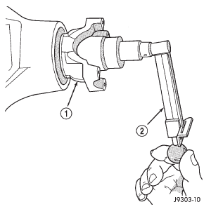
Fig. 18 Check Pinion Gear Rotation Torque
2 - INCH POUND TORQUE WRENCH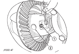
Fig. 19 Mate Shaft Lock Screw
2 - PINION GEAR MATE SHAFT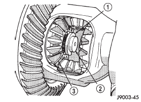
Fig. 20 Axle Shaft C-Clip Lock
2 - AXLE SHAFT
3 - SIDE GEARAxle shaft seal and bearing
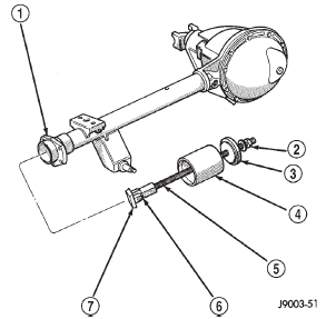
Fig. 21 Axle Shaft Bearing Removal
2 - NUT
3 - GUIDE PLATE
4 - GUIDE
5 - THREADED ROD
6 - ADAPTER
7 - FOOT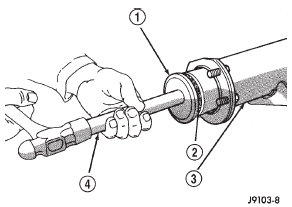
Fig. 22 Axle Shaft Seal Installation
2 - SEAL
3 - AXLE SHAFT TUBE
4 - SPECIAL TOOL C-4171Differential
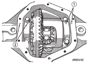
Fig. 23 Bearing Cap Identification
2 - INSTALLATION REFERENCE LETTERS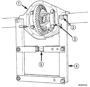
Fig. 24 Install Axle Housing Spreader
2 - DOWEL
3 - SAFETY HOLD DOWN
4 - SPECIAL TOOL W-129-B
5 - TURNBUCKLE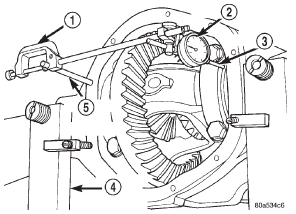
Fig. 25 Install Dial Indicator
2 - DIAL INDICATOR
3 - LEVER ADAPTER
4 - SPECIAL TOOL W-129-B
5 - SPECIAL TOOL C-3288-B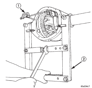
Fig. 26 Spread Axle Housing
2 - SPECIAL TOOL W-129-B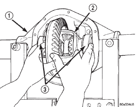
Fig. 27 Differential Case Removal
2 - DIFFERENTIAL CASE
3 - BEARING CUPS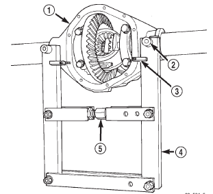
Fig. 28 Install Axle Housing Spreader
2 - DOWEL
3 - SAFETY HOLD DOWN
4 - SPECIAL TOOL W-129-B
5 - TURNBUCKLE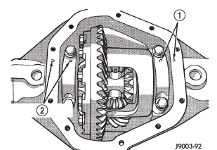
Fig. 29 Differential Bearing Cap Reference Let
2 - INSTALLATION REFERENCE LETTERS
 Rear axle. Pinion shaft seal. Collapsible spacer
 Differential side bearings. Ring gear. Pinion gear
Other materials:
Cd/dvd disc maintenance
To keep a CD/DVD in good condition, take the following
precautions:
1. Handle the disc by its edge; avoid touching the
surface.
2. If the disc is stained, clean the surface with a soft cloth,
wiping from center to edge.
3. Do not apply paper or tape to the disc; avoid scratching
the disc. ...