Jeep Cherokee (XJ): Blower motor relay. Blower motor resistor. Compressor
WARNING: ON VEHICLES EQUIPPED WITH AIRBAGS,
REFER TO GROUP 8M - PASSIVE
RESTRAINT SYSTEMS BEFORE ATTEMPTING ANY
STEERING WHEEL, STEERING COLUMN, OR
INSTRUMENT PANEL COMPONENT DIAGNOSIS OR
SERVICE. FAILURE TO TAKE THE PROPER PRECAUTIONS
COULD RESULT IN ACCIDENTAL AIRBAG
DEPLOYMENT AND POSSIBLE PERSONAL
INJURY.
(1) Disconnect and isolate the battery negative
cable.
(2) Roll the glove box down from the instrument
panel. Refer to Glove Box in Group 8E - Instrument
Panel Systems for the procedures.
(3) Reach through the instrument panel glove box
opening to locate the blower motor relay (Fig. 17).
(4) Unplug the blower motor relay from its wire
harness connector.
(5) Install the blower motor relay by aligning the
relay terminals with the cavities in the wire harness
connector and pushing the relay firmly into place.
1 - BLOWER MOTOR RELAY (6) Roll the glove box back up into the instrument
panel. Refer to Glove Box in Group 8E - Instrument
Panel Systems for the procedures.
(7) Connect the battery negative cable.
(8) Test the relay operation. WARNING: ON VEHICLES EQUIPPED WITH AIRBAGS,
REFER TO GROUP 8M - PASSIVE
RESTRAINT SYSTEMS BEFORE ATTEMPTING ANY
STEERING WHEEL, STEERING COLUMN, OR
INSTRUMENT PANEL COMPONENT DIAGNOSIS OR
SERVICE. FAILURE TO TAKE THE PROPER PRECAUTIONS
COULD RESULT IN ACCIDENTAL AIRBAG
DEPLOYMENT AND POSSIBLE PERSONAL
INJURY.
(1) Disconnect and isolate the battery negative
cable.
(2) Remove the kick cover from the heater-A/C
housing. See Kick Cover in this group for the procedures.
(3) Pull out the lock on the blower motor resistor
wire harness connector to unlock the connector latch
(Fig. 18).
(4) Depress the latch on the blower motor resistor
wire harness connector and unplug the connector
from the resistor.
(5) Remove the two screws that secure the resistor
to the heater-A/C housing.
(6) Remove the resistor from the heater-A/C housing.
(7) Reverse the removal procedures to install.
Tighten the mounting screws to 2.2 N·m (20 in lbs.).
1 - SCREWS The compressor may be removed and repositioned
without disconnecting the refrigerant lines or discharging
the refrigerant system. Discharging is not
necessary if servicing the compressor clutch or clutch
coil, the engine, the cylinder head, or the generator.
WARNING: REVIEW THE WARNINGS AND CAUTIONS
IN THE FRONT OF THIS GROUP BEFORE
PERFORMING THE FOLLOWING OPERATION. REMOVAL (1) Recover the refrigerant from the refrigerant
system. See Refrigerant Recovery in this group for
the procedures.
(2) Disconnect and isolate the battery negative
cable.
(3) Remove the serpentine drive belt. Refer to
Group 7 - Cooling System for the procedures.
(4) Unplug the compressor clutch coil wire harness
connector.
(5) Remove the suction and discharge refrigerant
line manifold from the compressor. See Suction and
Discharge Line in this group for the procedures.
Install plugs in, or tape over all of the opened refrigerant
fittings.
(6) Remove the four bolts that secure the compressor
to the mounting bracket (Fig. 19).
(7) Remove the compressor from the mounting
bracket.
1 - BOLT INSTALLATION NOTE: If a replacement compressor is being
installed, be certain to check the refrigerant oil
level. See Refrigerant Oil Level in this group for the
procedures. Use only refrigerant oil of the type recommended
for the compressor in the vehicle.
(1) Install the compressor to the mounting bracket.
Tighten the four mounting bolts as follows:
² All 2.5L and 4.0L engines - 27 N·m (20 ft. lbs.)
(2) Remove the tape or plugs from all of the
opened refrigerant line fittings. Install the suction
and discharge line manifold to the compressor. See
Suction and Discharge Line in this group for the procedures.
(3) Install the serpentine drive belt. Refer to
Group 7 - Cooling System for the procedures.
(4) Plug in the compressor clutch coil wire harness
connector.
(5) Connect the battery negative cable.
(6) Evacuate the refrigerant system. See Refrigerant
System Evacuate in this group for the procedures.
(7) Charge the refrigerant system. See Refrigerant
System Charge in this group for the procedures.Blower motor relay
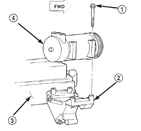
Fig. 17 Blower Motor Relay Remove/Install
2 - VACUUM HARNESS
3 - HEATER-A/C WIRE HARNESS CONNECTOR
4 - HEATER-A/C HOUSINGBlower motor resistor
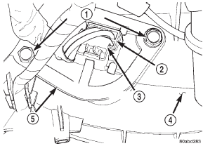
Fig. 18 Blower Motor Resistor Remove/Install
2 - WIRE HARNESS CONNECTOR
3 - CONNECTOR LOCK
4 - HEATER-A/C HOUSING
5 - BLOWER MOTOR RESISTORCompressor
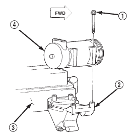
Fig. 19 Compressor Remove/Install - All 2.5L/4.0L Engines
2 - MOUNTING BRACKET
3 - ENGINE
4 - COMPRESSOR
 Accumulator. Blend-air door motor. Blower motor

Other materials:
Publication order forms
To order the following manuals, you may use either the
website or the phone numbers listed below. Visa, Mastercard,
American Express, and Discover orders are accepted.
If you prefer mailing your payment, please call
for an order form.
NOTE: A street address is required when ordering
manuals ...