Jeep Cherokee (XJ): Camshaft pin replacement
REMOVAL
WARNING: DO NOT LOOSEN THE RADIATOR DRAIN COCK WITH THE SYSTEM HOT AND PRESSURIZED BECAUSE SERIOUS BURNS FROM COOLANT CAN OCCUR.
(1) Disconnect negative cable from battery.
(2) Drain the radiator. DO NOT waste reusable coolant. Drain the coolant into a clean container.
(3) Remove the fan and shroud.
(4) Disconnect the radiator overflow tube, radiator hoses, automatic transmission fluid cooler pipes (if equipped).
(5) Remove the radiator.
(6) If equipped with air conditioning: CAUTION: DO NOT loosen or disconnect any air conditioner system fittings. Move the condenser and receiver/drier aside as a complete assembly.
(a) Remove the A/C compressor serpentine drive belt idler pulley.
(b) Disconnect and remove the generator.
(c) Remove the A/C condenser attaching bolts and move the condenser and receiver/drier assembly up and out of the way.
(7) Remove the serpentine drive belt.
(8) Remove the crankshaft vibration damper.
(9) Remove the timing case cover. Clean the gasket material from the cover.
(10) Rotate crankshaft until the crankshaft sprocket timing mark is closest to and on the center line with the camshaft sprocket timing mark (Fig.
72).
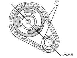
Fig. 72 Timing Chain Alignment
1 - TIMING MARKS
(11) Remove camshaft sprocket retaining bolt.
(12) Remove the crankshaft oil slinger.
(13) Remove the sprockets and chain as an assembly (Fig. 73).
CAUTION: The following procedural step must be accomplished to prevent the camshaft from damaging the rear camshaft plug during pin installation.
(14) Inspect the damaged camshaft pin.
(15) If the pin is a spring-type pin, remove the broken pin by inserting a self-tapping screw into the pin and carefully pulling the pin from the camshaft.
(16) If the pin is a dowel-type pin, center-punch it.
Ensure the exact center is located when centerpunching the pin.
CAUTION: Cover the opened oil pan area to prevent metal chips from entering the pan.
(17) Drill into the pin center with a 4 mm (5/32 inch) drill bit.
(18) Insert a self-tapping screw into the drilled pin and carefully pull the pin from the camshaft.
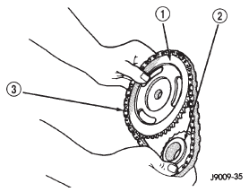
Fig. 73 Camshaft and Crankshaft Sprocket and Chain
1 - CAMSHAFT SPROCKET
2 - CRANKSHAFT SPROCKET
3 - CHAIN
INSTALLATION
(1) Clean the camshaft pin hole.
(2) Compress the center of the replacement spring pin with vise grips.
(3) Carefully drive the pin into the camshaft pin hole until it is seated.
(4) Install the camshaft sprocket, crankshaft sprocket and timing chain with the timing marks aligned (Fig. 72).
(5) To verify correct installation of the timing chain, turn the crankshaft to position the camshaft sprocket timing mark as shown in (Fig. 74). Count the number of chain pins between the timing marks of both sprockets. There must be 20 pins.
(6) Install the crankshaft oil slinger.
(7) Tighten the camshaft sprocket bolt to 108 N·m (80 ft. lbs.) torque.
(8) Check the valve timing.
(9) Coat both sides of the replacement timing case cover gasket with gasket sealer. Apply a 3 mm (1/8 inch) bead of Mopar Silicone Rubber Adhesive Sealant, or equivalent to the joint formed at the timing case cover and cylinder block.
(10) Position the timing case cover on the oil pan gasket and the cylinder block.
(11) Place Timing Case Cover Alignment and Seal Installation Tool 6139 in the crankshaft opening of the cover (Fig. 75).
(12) Install the timing case cover-to-cylinder block bolts. Install the oil pan-to-timing case cover bolts.
(13) Tighten the 1/4 inch cover-to-block bolts to 7 N·m (60 in. lbs.) torque. Tighten the 5/16 inch front cover-to-block bolts to 22 N·m (192 in. lbs.) torque.
Tighten the oil pan-to-cover 1/4 inch bolts to 14 N·m (120 in. lbs.) torque. Tighten the oil pan-to-cover 5/16 inch bolts to 18 N·m (156 in. lbs.) torque.
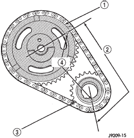
Fig. 74 Verify Crankshaft-Camshaft Installation
1 - CAMSHAFT SPROCKET
2 - 20 PINS
3 - CRANKSHAFT SPROCKET
4 - TIMING MARKS
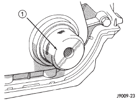
Fig. 75 Timing Case Cover Alignment and Seal Installation Tool 6139
1 - TIMING CASE COVER ALIGNMENT AND SEAL INSTALLATION TOOL
(14) Remove the cover alignment tool and install a replacement oil seal into the cover.
(15) Install the vibration damper on the crankshaft.
(16) Lubricate and tighten the damper bolt to 108 N·m (80 ft. lbs.) torque.
(17) If equipped with air conditioning: (a) Install the A/C compressor serpentine drive belt idler pulley.
(b) Install the generator.
(c) Install the A/C condenser and receiver/drier assembly.
(18) Install the serpentine drive belt on the pulleys and tighten (refer to Group 7, Cooling System for the specifications and procedures).
(19) Install the radiator. Connect the radiator hoses and automatic transmission fluid cooler pipes, if equipped. Fill the cooling system.
(20) Install the fan and shroud.
(21) Connect negative cable to battery.
 Timing case cover. Timing chain and sprockets. Camshaft
 Camshaft bearings. Crankshaft main bearings. Oil pan
Other materials:
Heater-A/C housing
The heater-A/C housing assembly must be removed
from the vehicle and the two halves of the housing
separated for service access of the heater core, evaporator
coil, blend-air door, and each of the various
mode control doors.
WARNING: ON VEHICLES EQUIPPED WITH AIRBAGS,
REFER TO GROUP 8M - PASSI ...