Jeep Cherokee (XJ): Direct clutch
DISASSEMBLY
(1) Remove direct clutch from forward clutch (Fig.
238).
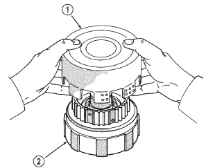
Fig. 238 Separate Direct Clutch From Forward Clutch
1 - DIRECT CLUTCH
2 - FORWARD CLUTCH
(2) Remove clutch drum thrust washer (Fig. 239).
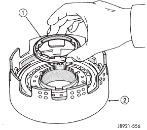
Fig. 239 Removing Clutch Drum Thrust Washer
1 - THRUST WASHER
2 - CLUTCH DRUM
(3) Check clutch piston stroke length as outlined in following steps.
(4) Mount direct clutch on overdrive support assembly (Fig. 240).
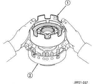
Fig. 240 Mount Direct Clutch On Overdrive Support
1 - DIRECT CLUTCH
2 - OVERDRIVE SUPPORT
(5) Mount dial indicator on clutch and position indicator plunger on clutch piston (Fig. 241).
(6) Apply 57-114 psi air pressure through feed hole in overdrive support and note piston stroke length (Fig. 241). Check stroke at least twice.
(7) Piston stroke length should be 1.37 mm - 1.67 mm (0.054 - 0.065 in.). If stroke length is incorrect, either the clutch pack retainer or clutch discs will have to be replaced.
(8) Remove clutch pack snap ring and remove retainer and clutch pack from drum (Fig. 242).
(9) Compress clutch piston return springs with tool 7538 and remove clutch piston snap ring (Fig. 243).
(10) Remove compressor tool and return spring.
(11) Remove clutch piston. Remount clutch on overdrive support (Fig. 244). Apply compressed air through piston feed hole in support to remove piston.
Use only enough air to ease piston out.
(12) Remove and discard clutch piston O-rings.
(13) Measure clutch disc thickness. Minimum allowable thickness is 1.84 mm (0.0724 in). Replace clutch pack if any disc is below minimum thickness.
(14) Measure free length of piston return springs with springs in retainer (Fig. 245). Length should be 21.32 mm (0.839 in.). Replace return springs if not within specification.
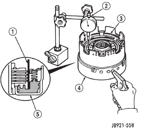
Fig. 241 Checking Direct Clutch Piston Stroke Length
1 - INDICATOR PLUNGER
2 - DIAL INDICATOR
3 - CLUTCH PISTON
4 - OVERDRIVE SUPPORT
5 - CLUTCH PISTON
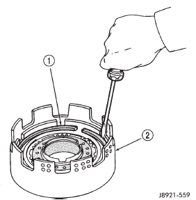
Fig. 242 Removing Clutch Pack Snap Ring
1 - CLUTCH PACK SNAP RING
2 - DIRECT CLUTCH DRUM
(15) Check clutch piston check ball (Fig. 246).
Shake piston to see if ball moves freely. Then check ball seating by applying low pressure compressed air
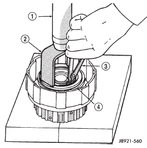
Fig. 243 Removing Piston Return Spring
1 - PRESS RAM
2 - COMPRESSOR TOOL
3 - SNAP RING PLIERS
4 - RETURN SPRING
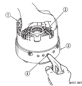
Fig. 244 Removing Direct Clutch Piston
1 - DIRECT CLUTCH DRUM
2 - CLUTCH PISTON
3 - OVERDRIVE SUPPORT
4 - SUPPORT FEED HOLE
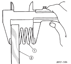
Fig. 245 Checking Piston Return Spring Length
1 - PISTON RETURN SPRINGS
2 - SPRING RETAINER
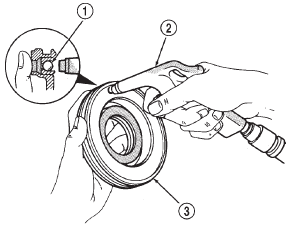
Fig. 246 Testing Piston Check Ball Seating
1 - PISTON CHECK BALL
2 - USE LOW-PRESSURE AIR TO CHECK SEATING
3 - DIRECT CLUTCH PISTON
(16) Measure inside diameter of clutch drum bushing.
Inside diameter should be no more than 53.97 mm (2.1248 in.). Replace drum if bushing inside diameter is greater than specified.
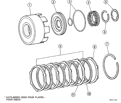
Fig. 247 Direct Clutch Components
1 - DIRECT CLUTCH DRUM
2 - DIRECT CLUTCH PISTON
3 - O-RINGS
4 - PISTON RETURN SPRINGS
5 - CLUTCH DRUM THRUST WASHER
6 - CLUTCH PISTON SNAP RING
7 - CLUTCH PACK SNAP RING
8 - RETAINER
9 - CLUTCH PACK
10 - CLUTCH DISC*
11 - CLUTCH PLATE*
ASSEMBLY
(1) Lubricate and install replacement O-rings on clutch piston (Fig. 247).
(2) Install clutch piston in drum and install return springs on piston.
(3) Compress piston return springs with Tool 7538 and install snap ring (Fig. 243). Be sure snap ring end gap is not aligned with spring retainer tab.
(4) Install clutch discs and plates (Fig. 248).
Install plate then disc until all plates and discs are installed. Four plates and discs are required.
(5) Install clutch pack retainer in drum (Fig. 249).
(6) Install clutch pack snap ring (Fig. 249).
(7) Check snap ring position. If necessary, shift snap ring until end gap is not aligned with any notches in clutch drum (Fig. 250).
(8) Lubricate clutch drum thrust washer with petroleum jelly and install it in drum (Fig. 240).
(9) Mount direct clutch assembly on forward clutch assembly and check assembled height (Fig. 251).
Height should be 70.3 to 71.5 mm (2.767 to 2.815 in.).
(10) If assembled height is incorrect, clutches are not seated.
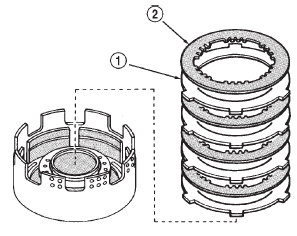
Fig. 248 Installing Direct Clutch Discs And Plates
1 - CLUTCH PLATES
2 - CLUTCH DISCS
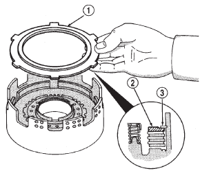
Fig. 249 Install Clutch Pack Retainer
1 - CLUTCH PACK RETAINER
2 - RETAINER
3 - SNAP RING
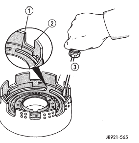
Fig. 250 Adjusting Clutch Pack Snap Ring Position
1 - CLUTCH PACK SNAP RING
2 - DRUM NOTCH
3 - SHIFT SNAP RING END GAP AWAY FROM DRUM NOTCHES
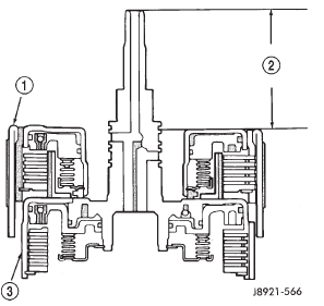
Fig. 251 Checking Direct Clutch Assembled Height
1 - DIRECT CLUTCH
2 - HEIGHT SHOULD BE 70.3-71.5 mm (2.767-2.815 in.)
3 - FORWARD CLUTCH
 Oil pump. Overdrive planetary gear and
clutch. Overdrive support
Oil pump. Overdrive planetary gear and
clutch. Overdrive support

Other materials:
Vehicle loading
Certification Label
As required by National Highway Traffic Safety Administration
regulations, your vehicle has a certification label
affixed to the driver's side door or pillar.
This label contains the month and year of manufacture,
Gross VehicleWeight Rating (GVWR), Gross AxleWeight
Rating ...