Jeep Cherokee (XJ): Distributor-2.5L engine
The distributor contains an internal oil seal that prevents oil from entering the distributor housing.
The seal is not serviceable.
Factory replacement distributors are equipped with a plastic alignment pin already installed. The pin is located in an access hole on the bottom of the distributor housing (Fig. 32). It is used to temporarily lock the rotor to the cylinder number 1 position during installation. The pin must be removed after installing the distributor.
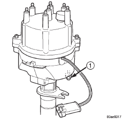
Fig. 32 Plastic Alignment Pin-2.5L Engine
1 - PLASTIC ALIGNMENT PIN
The camshaft position sensor is located in the distributor (Fig. 33). For removal/installation procedures, refer to Camshaft Position Sensor. Distributor removal is not necessary for sensor removal.
Refer to (Fig. 33) for an exploded view of the distributor.
A fork with a slot is supplied on the bottom of the distributor housing where the housing base seats against the engine block (Fig. 33). The centerline of the slot aligns with the distributor holddown bolt hole in the engine block. Because of the fork, the distributor cannot be rotated. Distributor rotation is not necessary as all ignition timing requirements are handled by the Powertrain Control Module (PCM).
The position of the distributor determines fuel synchronization only. It does not determine ignition timing.
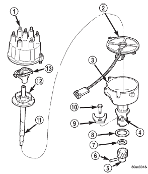
Fig. 33 Distributor-2.5L Engine-Typical
1 - CAP
2 - CAMSHAFT POSITION SENSOR
3 - HOUSING
4 - FORK WITH SLOT
5 - DRIVE GEAR
6 - ROLL PIN
7 - WASHER
8 - GASKET
9 - HOLDDOWN CLAMP
10 - HOLDDOWN BOLT
11 - SHAFT
12 - PULSE RING
13 - ROTOR
NOTE: Do not attempt to modify this fork to attain ignition timing.
REMOVAL
(1) Disconnect negative battery cable at battery.
(2) Disconnect coil secondary cable at coil.
(3) Remove distributor cap from distributor (2 screws). Do not remove cables from cap. Do not remove rotor.
(4) Disconnect distributor wiring harness from main engine harness.
(5) Remove cylinder number 1 spark plug.
(6) Hold a finger over open spark plug hole. Rotate engine at vibration dampener bolt until compression (pressure) is felt.
(7) Slowly continue to rotate engine. Do this until timing index mark on vibration damper pulley aligns with Top Dead Center (TDC) mark (0 degree) on timing degree scale (Fig. 34). Always rotate engine in direction of normal rotation. Do not rotate engine backward to align timing marks.
(8) On models equipped with A/C, remove electrical cooling fan and shroud assembly from radiator.
Refer to Group 7, Cooling System for procedures.
(9) This will provide room to turn engine crankshaft with a socket and ratchet using vibration damper bolt.
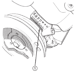
Fig. 34 Align Timing Marks-2.5L Engine
1 - CRANKSHAFT VIBRATION DAMPER TIMING MARK
(10) Remove distributor holddown bolt and clamp.
(11) Remove distributor from engine by slowly lifting straight up.
(12) Note that rotor will rotate slightly in a counterclockwise direction while lifting up distributor.
The oil pump gear will also rotate slightly in a counterclockwise direction while lifting up distributor.
This is due to the helical cut gears on distributor and camshaft.
(13) Note removed position of rotor during distributor removal. During installation, this will be referred to as the Pre-position.
(14) Observe slot in oil pump gear through hole on side of engine. It should be slightly before (counterclockwise of) 10 o'clock position (Fig. 35).
(15) Remove and discard the old distributor-to-engine block gasket.
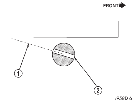
Fig. 35 Slot At 10 O'clock Position-2.5L Engine
1 - 10 0'CLOCK POSITION
2 - OIL PUMP SLOT
INSTALLATION
(1) If engine crankshaft has been rotated after distributor removal, cylinder number 1 must be returned to its proper firing stroke. Refer to previous REMOVAL Step 5 and Step 6. These steps must be done before installing distributor.
(2) Check position of slot on oil pump gear. On the 2.5L engine, it should be just slightly before (counterclockwise of) 10 o'clock position (Fig. 35). If not, place a flat blade screwdriver into oil pump gear and rotate it into proper position.
(3) Factory replacement distributors are equipped with a plastic alignment pin already installed (Fig.
32). This pin is used to temporarily hold rotor to cylinder number 1 firing position during distributor installation. If pin is in place, proceed to Step 8. If not, proceed to next step.
(4) If original distributor is to be reinstalled, such as during engine overhaul, the plastic pin will not be available. A 3/16 inch drift pin punch tool may be substituted for plastic pin.
(5) Remove camshaft position sensor from distributor housing. Lift straight up.
(6) Four different alignment holes are provided on plastic ring (Fig. 36). Note that 2.5L and 4.0L engines have different alignment holes (Fig.
36).
(7) Rotate distributor shaft and install pin punch tool through proper alignment hole in plastic ring (Fig. 36) and into mating access hole in distributor housing. This will prevent distributor shaft and rotor from rotating.
(8) Clean distributor mounting hole area of engine block.
(9) Install new distributor-to-engine block gasket (Fig. 33).
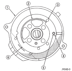
Fig. 36 Pin Alignment Holes-2.5L Engine
1 - DISTRIBUTOR HOUSING (TOP VIEW)
2 - PULSE RING
3 - 4.0L 6-CYLINDER ENGINE ALIGN. HOLE
4 - 2.5L 4-CYLINDER ENGINE ALIGN. HOLE
5 - MATING ACCESS HOLE IN DISTRIBUTOR HOUSING
6 - PLASTIC RING
(10) Install rotor to distributor shaft.
(11) Pre-position distributor into engine while holding centerline of base slot in 1 o'clock position (Fig. 37). Continue to engage distributor into engine.
The rotor and distributor will rotate clockwise during installation. This is due to the helical cut gears on distributor and camshaft. When distributor is fully seated to engine block, the centerline of base slot should be aligned to clamp bolt mounting hole on engine (Fig. 38). The rotor should also be pointed slightly past (clockwise of) 3 o'clock position.
It may be necessary to rotate rotor and distributor shaft (very slightly) to engage distributor shaft with slot in oil pump gear. The same may have to be done to engage distributor gear with camshaft gear.
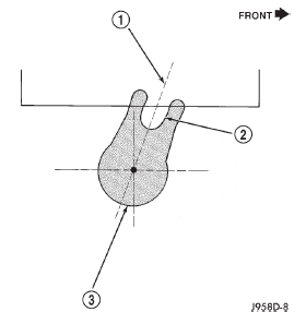
Fig. 37 Distributor Pre-position-2.5L Engine
1 - 1 O'CLOCK POSITION
2 - BASE SLOT
3 - DISTRIBUTOR BASE
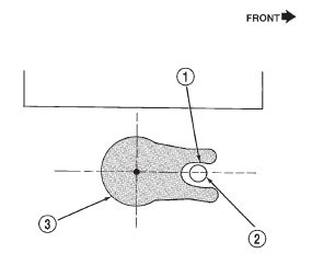
Fig. 38 Distributor Engaged Position-2.5L Engine
1 - DISTRIBUTOR BASE SLOT
2 - CLAMP BOLT MOUNTING HOLE (ON ENGINE)
3 - DISTRIBUTOR BASE
The distributor is correctly installed when:
- rotor is pointed at 3 o'clock position.
- plastic alignment pin (or pin punch tool) is still installed to distributor.
- number 1 cylinder piston is set at top dead center (TDC) (compression stroke).
- centerline of slot at base of distributor is aligned to centerline of distributor holddown bolt hole on engine. In this position, the holddown bolt should easily pass through slot and into engine.
No adjustments are necessary. Proceed to next step.
(12) Install distributor holddown clamp and bolt.
Tighten bolt to 23 N·m (17 ft. lbs.) torque.
(13) Remove pin punch tool from distributor. Or, if plastic alignment pin was used, remove it straight down from bottom of distributor. Discard plastic pin.
(14) If removed, install camshaft position sensor to distributor. Align wiring harness grommet to notch in distributor housing.
(15) Install rotor.
CAUTION: If the distributor cap is incorrectly positioned on distributor housing, cap or rotor may be damaged when engine is started.
(16) Install distributor cap. Tighten distributor cap holddown screws to 3 N·m (26 in. lbs.) torque.
(17) If removed, install spark plug cables to distributor cap. For proper firing order, refer to Engine Firing Order.
(18) Connect distributor wiring harness to main engine harness.
(19) Connect battery cable to battery.
 Camshaft position sensor-4.0L
engine
 Ignition switch and key cylinder
Other materials:
Adjustments
Brake lamp switch
(1) Press and hold brake pedal in applied position.
(2) Pull switch plunger all the way out to fully
extended position.
(3) Release brake pedal. Then pull pedal lightly
rearward. Pedal will set plunger to correct position
as pedal pushes plunger into switch body. Switch wi ...
