Jeep Cherokee (XJ): Ignition switch and key cylinder
The ignition key must be in the key cylinder for cylinder removal. The key cylinder must be removed first before removing ignition switch.
KEY CYLINDER REMOVAL
(1) Disconnect negative battery cable at battery.
(2) If equipped with an automatic transmission, place shifter in PARK position.
(3) Rotate key to ON position.
(4) A release tang is located on bottom of key cylinder (Fig. 39).
(5) Position a small screwdriver or pin punch into tang access hole on bottom of steering column lower cover (Fig. 40).
(6) Push the pin punch up while pulling key cylinder from steering column.
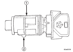
Fig. 39 Key Cylinder Release Tang
1 - KEY CYLINDER
2 - RELEASE TANG
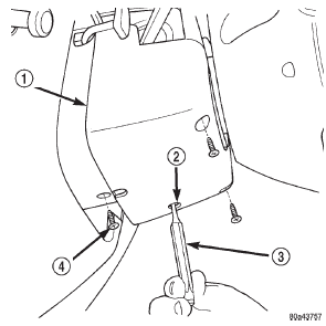
Fig. 40 Key Cylinder and Cover Removal
1 - LOWER COVER
2 - ACCESS HOLE
3 - PIN PUNCH
4 - COVER SCREWS (3)
IGNITION SWITCH REMOVAL
(1) Remove key cylinder. Refer to previous steps.
(2) Remove lower steering column cover screws and remove cover (Fig. 40).
(3) Remove ignition switch mounting screw (Fig.
43). Use tamper proof torx bit (Snap-Ont SDMTR10 or equivalent) to remove the screw.
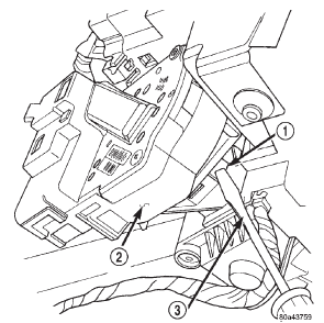
Fig. 41 Ignition Switch Lock Tab
1 - LOCK TAB
2 - IGNITION SWITCH
3 - SCREWDRIVER
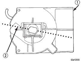
Fig. 42 Switch In ON Position
1 - IGNITION SWITCH
2 - ROTATE TO ON POSITION
(4) Using a small screwdriver, push on locking tab (Fig. 41) and remove switch from steering column.
(5) Disconnect two electrical connectors at rear of ignition switch (Fig. 43).
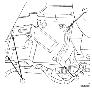
Fig. 43 Ignition Switch Removal/Installation
1 - TAMPER PROOF SCREW
2 - IGNITION SWITCH
3 - ELECTRICAL CONNECTORS
IGNITION SWITCH INSTALLATION
(1) Before installing ignition switch, rotate the slot in the switch to the ON position (Fig. 42).
(2) Connect two electrical connectors to rear of ignition switch. Make sure that locking tabs are fully seated into wiring connectors.
(3) Position switch to column and install tamper proof screw. Tighten screw to 3 N·m (26 in. lbs.).
(4) Install steering column lower cover.
KEY CYLINDER INSTALLATION
(1) If equipped with an automatic transmission, place shifter in PARK position.
(2) Position key cylinder into steering column as it would normally be in the ON position.
(3) Press key cylinder into column until it snaps into position.
(4) Check mechanical operation of switch. Automatic Transmission: Be sure transmission lever is locked in PARK position after key removal. If key is difficult to rotate or is difficult to remove, the shift lever-to-steering column cable may be out of adjustment or defective. Refer to Group 21, Transmission for procedures. Manual Transmission: Be sure key cannot be removed until release lever is operated. If key can be removed, release lever mechanism may be defective. Release lever mechanism is not serviced separately. If repair is necessary, the steering column must be replaced. Refer to Group 19, Steering for procedures.
(5) Connect negative cable to battery.
(6) Check electrical operation of switch.
Other materials:
30RH automatic transmission
DESCRIPTION
The 30RH automatic transmission is used with the
2.5L engine (Fig. 1). The 30RH is three speed transmissions
with a lock-up clutch in the torque converter.
The transmissions contain a front and rear
clutch which function as the input driving components.
They also contain the ki ...


