Jeep Cherokee (XJ): Fuel filter/fuel pressure regulator. Fuel pump module. Fuel pump inlet filter
The combination Fuel Filter/Fuel Pressure Regulator
is located on the fuel pump module. The fuel
pump module is located on top of fuel tank.
The filter/regulator may be removed without
removing fuel pump module although fuel tank must
be removed. REMOVAL (1) Remove fuel tank. Refer to Fuel Tank Removal/
Installation.
(2) Clean area around filter/regulator.
(3) Disconnect fuel line at filter/regulator. Refer to
Quick-Connect Fittings in this group for procedures.
(4) Remove retainer clamp from top of filter/regulator
(Fig. 21). Clamp snaps to tabs on pump module.
Discard old clamp.
(5) Pry filter/regulator from top of pump module
with 2 screwdrivers. Unit is snapped into module.
(6) Discard gasket below filter/regulator (Fig. 22).
(7) Before discarding filter/regulator assembly,
inspect assembly to verify that o-rings (Fig. 23) are
intact. If the smallest of the two o-rings can not be
found on bottom of filter/regulator, it may be necessary
to remove it from the fuel inlet passage in fuel
pump module.
1 - RETAINER CLAMP
1 - TOP OF MODULE INSTALLATION (1) Clean recessed area in pump module where filter/
regulator is to be installed.
(2) Obtain new filter/regulator (two new o-rings
should already be installed).
(3) Apply a small amount of clean engine oil to
o-rings. Do not install o-rings separately into
fuel pump module. They will be damaged when
installing filter/regulator.
1 - FUEL FILTER/FUEL PRESSURE REGULATOR (4) Install new gasket to top of fuel pump module.
(5) Press new filter/regulator into top of pump
module until it snaps into position (a positive click
must be heard or felt).
(6) The arrow (Fig. 21) molded into top of fuel
pump module should be pointed towards front of
vehicle (12 o'clock position).
(7) Rotate filter/regulator until fuel supply tube
(fitting) is pointed towards front of vehicle (12 o'clock
position).
(8) Install new retainer clamp (clamp snaps over
top of filter/regulator and locks to flanges on pump
module).
(9) Connect fuel line at filter/regulator. Refer to
Quick-Connect Fittings in this group for procedures.
(10) Install fuel tank. Refer to Fuel Tank Removal/
Installation. Fuel tank removal will be necessary for fuel pump
module removal. REMOVAL WARNING: THE FUEL SYSTEM IS UNDER A CONSTANT
PRESSURE EVEN WITH ENGINE OFF.
BEFORE SERVICING THE FUEL PUMP MODULE,
FUEL SYSTEM PRESSURE MUST BE RELEASED. (1) Drain fuel tank and remove tank. Refer to the
Fuel Tank Removal/Installation section of this group.
(2) Thoroughly wash and clean area around pump
module to prevent contaminants from entering tank.
(3) Disconnect fuel line at filter/regulator. Refer to
Quick-Connect Fittings in this group for procedures.
(4) The plastic fuel pump module locknut is
threaded onto fuel tank (Fig. 24). Install Special Tool
6856 to fuel pump module locknut and remove locknut
(Fig. 25). The fuel pump module will spring up
when locknut is removed.
(5) Remove module from fuel tank.
1 - ROLLOVER VALVE INSTALLATION CAUTION: Whenever fuel pump module is serviced,
module gasket must be replaced.
(1) Thoroughly clean locknut threads and mating
fuel tank threads. Use a soap/water solution. Do not
use carburetor cleaner to clean threads.
(2) Using a new gasket, position gasket and fuel
pump module into opening in fuel tank.
(3) Apply clean water to gasket and locknut
threads.
(4) Position locknut over top of fuel pump module.
1 - SPECIAL TOOL 6856 (5) Rotate module until molded arrow (Fig. 24) is
pointed toward front of vehicle (12 o'clock position).
This step must be done to prevent float/float rod
assembly from contacting sides of fuel tank.
(6) Install Special Tool 6856 to locknut.
(7) Tighten locknut to 74 N·m (55 ft. lbs.) torque.
(8) Rotate fuel filter/fuel pressure regulator until
its fitting is pointed toward front of vehicle (12
o'clock position).
(9) Connect fuel line at filter/regulator. Refer to
Quick-Connect Fittings in this group for procedures.
(10) Install fuel tank. Refer to Fuel Tank Installation
in this section. The fuel pump inlet filter (strainer) is located on
the bottom of fuel pump module (Fig. 26). The fuel
pump module is located on top of fuel tank. REMOVAL (1) Remove fuel tank. Refer to Fuel Tank Removal/
Installation.
(2) Remove fuel pump module. Refer to Fuel Pump
Module Removal/Installation.
(3) Remove filter by prying from bottom of module
with 2 screwdrivers. Filter is snapped to module.
(4) Clean bottom of pump module. INSTALLATION (1) Snap new filter to bottom of module.
(2) Install fuel pump module. Refer to Fuel Pump
Module Removal/Installation.
(3) Install fuel tank. Refer to Fuel Tank Removal/
Installation.
1 - FUEL PUMP MODULEFuel filter/fuel pressure regulator
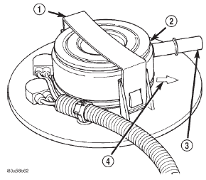
Fig. 21 Fuel Filter/Fuel Pressure Regulator
2 - FUEL FILTER/FUEL PRESSURE REGULATOR
3 - FUEL SUPPLY TUBE
4 - ALIGNMENT ARROW
Fig. 22 Fuel Filter/Fuel Pressure Regulator Gasket
2 - GASKET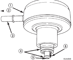
Fig. 23 Fuel Filter/Fuel Pressure Regulator O-Rings
2 - TO FUEL INJECTORS
3 - FUEL SUPPLY TUBE
4 - O-RINGS
5 - FUEL INLET FROM PUMP
6 - FUEL RETURN TO TANKFuel pump module
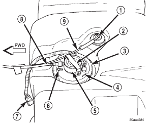
Fig. 24 Top View of Fuel Tank and Fuel Pump Module
2 - RETAINER CLAMP
3 - LOCKNUT
4 - FUEL PUMP MODULE
5 - FUEL FILTER/FUEL PRESSURE REGULATOR
6 - ALIGNMENT ARROW
7 - PIGTAIL HARNESS
8 - FUEL SUPPLY TUBE
9 - EVAP CANISTER VENT LINE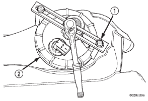
Fig. 25 Locknut Removal/Installation-Typical
2 - LOCKNUTFuel pump inlet filter
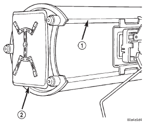
Fig. 26 Fuel Pump Inlet Filter
2 - FUEL PUMP INLET FILTER
Other materials:
Hood hinge. Hood latch. Hood latch striker
Hood hinge
REMOVAL
(1) Raise and support hood.
(2) Using a grease pencil or equivalent, mark position
of hood.
(3) Remove seal from hinge base (Fig. 4).
(4) Remove hinge retaining nuts from studs.
Fig. 4 Hood Hinge and Seal
1 - HINGE
2 - SEAL
3 - HINGE BASE
4 - DASH PANEL
5 - NU ...


