Jeep Cherokee (XJ): Removal and installation
REMOVAL WARNING: DISCONNECT NEGATIVE CABLE FROM
BATTERY BEFORE REMOVING BATTERY OUTPUT
WIRE (B+ WIRE) FROM GENERATOR. FAILURE TO
DO SO CAN RESULT IN INJURY OR DAMAGE TO
ELECTRICAL SYSTEM. (1) Disconnect negative battery cable at battery.
(2) Remove generator drive belt. Refer to Group 7,
Cooling System for procedures.
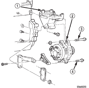
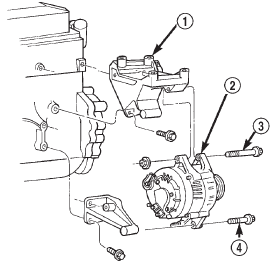
(3) Left Hand Drive (LHD) Vehicles Only: Remove
generator pivot and mounting bolts/nut (Fig. 1) or
(Fig. 2). Position generator for access to wire connectors.
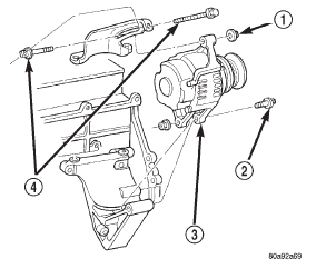
(4) Right Hand Drive (RHD) Vehicles Only:
Remove upper nut (generator adjustment nut) and
both belt adjustment bolts (Fig. 3). Remove generator
lower nut/bolt. Position generator for access to wire
connectors.
(5) If equipped, unsnap plastic cover from B+ terminal.
(6) Remove B+ terminal mounting nut at rear of
generator (Fig. 4). Disconnect terminal from generator.
(7) Disconnect field wire connector at rear of generator
by pushing on connector tab.
(8) Remove generator from vehicle.
1 - UPPER MOUNTING BRACKET
1 - UPPER MOUNTING BRACKET INSTALLATION (1) Position generator to engine and snap field
wire connector into rear of generator.
(2) Install B+ terminal to generator mounting
stud. Tighten mounting nut to 8.5 N·m (75 in. lbs.)
torque.
1 - UPPER NUT
1 - FIELD WIRES (3) If equipped, snap plastic cover to B+ terminal.
(4) LHD Vehicles: Install generator fasteners and
tighten as follows:
² Generator upper mounting bolt-55 N·m (41 ft.
lbs.) torque.
² Generator lower pivot bolt/nut-55 N·m (41 ft.
lbs.) torque.
CAUTION: Never force a belt over a pulley rim
using a screwdriver. The synthetic fiber of the belt
can be damaged.
CAUTION: When installing a serpentine accessory
drive belt, the belt MUST be routed correctly. The
water pump will be rotating in the wrong direction if
the belt is installed incorrectly, causing the engine
to overheat. Refer to belt routing label in engine
compartment, or refer to Belt Schematics in Group
7, Cooling System.
(5) LHD Vehicles: Install generator drive belt.
Refer to Group 7, Cooling System for procedures.
(6) RHD Vehicles: Install upper nut (generator
adjustment nut) and both belt adjustment bolts.
Install generator lower nut/bolt.
(7) RHD Vehicles: On vehicles equipped with RHD,
the generator is used to adjust the serpentine belt.
Refer to Group 7, Cooling System for belt routing,
belt adjustment and bolt tightening procedures.
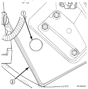
(8) Install negative battery cable to battery. The battery temperature sensor is located under
vehicle battery (Fig. 5) and is attached to a mounting
hole on battery tray.
1 - BATTERY TEMPERATURE SENSOR REMOVAL (1) Remove battery. Refer to Group 8A, Battery for
procedures.
(2) Disconnect sensor pigtail harness from engine
wire harness.
(3) Pry sensor straight up from battery tray
mounting hole. INSTALLATION (1) Feed pigtail harness through hole in top of battery
tray and press sensor into top of battery tray.
(2) Connect pigtail harness.
(3) Install battery. Refer to Group 8A, Battery for
procedures.Generator

Fig. 1 Remove/Install Generator-2.5L Engine
2 - GENERATOR
3 - UPPER BOLT
4 - LOWER BOLT
Fig. 2 Remove/Install Generator-4.0L Engine-LHD
2 - GENERATOR
3 - UPPER BOLT
4 - LOWER BOLT
Fig. 3 Remove/Install Generator-4.0L Engine-RHD
2 - LOWER BOLT
3 - GENERATOR
4 - BELT ADJUSTMENT BOLTS
Fig. 4 Generator Connectors-Typical Denso
2 - B+ (OUTPUT TERMINAL)
3 - FIELD WIRE CONNECTORBattery temperature sensor

Fig. 5 Battery Temperature Sensor
2 - BATTERY TRAY
Other materials:
Ducts and outlets
WARNING: ON VEHICLES EQUIPPED WITH AIRBAGS,
REFER TO GROUP 8M - PASSIVE
RESTRAINT SYSTEMS BEFORE ATTEMPTING ANY
STEERING WHEEL, STEERING COLUMN, OR
INSTRUMENT PANEL COMPONENT DIAGNOSIS OR
SERVICE. FAILURE TO TAKE THE PROPER PRECAUTIONS
COULD RESULT IN ACCIDENTAL AIRBAG
DEPLOYMENT AND POSSIBLE ...


