Jeep Cherokee (XJ): Timing chain and sprockets. Camshaft. Camshaft bearings
REMOVAL (1) Disconnect negative cable from battery.
(2) Remove the fan and shroud.
(3) Remove the serpentine drive belt.
(4) Remove the crankshaft vibration damper.
(5) Remove the timing case cover.
(6) Rotate crankshaft until the "0" timing mark is
closest to and on the center line with camshaft
sprocket timing mark (Fig. 61).
1 - CAMSHAFT SPROCKET (7) Remove the oil slinger from the crankshaft.
(8) Remove the camshaft sprocket bolt and washer
(Fig. 62).
1 - CAMSHAFT (9) Remove the crankshaft sprocket, camshaft
sprocket and timing chain as an assembly. (10) Installation of the timing chain with the timing
marks on the crankshaft and camshaft sprockets
properly aligned ensures correct valve timing. A worn
or stretched timing chain will adversely affect valve
timing. If the timing chain deflects more than 12.7
mm (1/2 inch) replace it. INSTALLATION Assemble the timing chain, crankshaft sprocket
and camshaft sprocket with the timing marks
aligned (Fig. 61).
(1) Apply Mopar Silicone Rubber Adhesive Sealant
to the keyway in the crankshaft and insert the key.
With the key in the keyway on the crankshaft, install
the assembly on the crankshaft and camshaft.
(2) Install the camshaft sprocket bolt and washer
(Fig. 62). Tighten the bolt to 68 N·m (50 ft. lbs.)
torque.
(3) To verify correct installation of the timing
chain, rotate the crankshaft 2 revolutions. The camshaft
and crankshaft sprocket timing mark should
align (Fig. 61).
(4) Install the crankshaft oil slinger.
(5) Replace the oil seal in the timing case cover.
(6) Install the timing case cover and gasket.
(7) With the key installed in the crankshaft keyway,
install the vibration damper, washer and bolt.
Lubricate and tighten the bolt to 108 N·m (80 ft. lbs.)
torque.
(8) Install the serpentine drive belt. (refer to
Group 7, Cooling System for the proper procedure).
(9) Install the fan and hub assembly. Install the
shroud.
(10) Connect negative cable to battery. REMOVAL WARNING: THE COOLANT IN A RECENTLY OPERATED
ENGINE IS HOT AND PRESSURIZED.
RELEASE THE PRESSURE BEFORE REMOVING
THE DRAIN COCK, CAP AND DRAIN PLUGS.
(1) Disconnect negative cable from battery.
(2) Drain the cooling system. DO NOT waste reusable
coolant. If the solution is clean, drain it into a
clean container for reuse.
(3) Remove the radiator or radiator and condenser,
if equipped with A/C (refer to Group 7, Cooling System
for the proper procedure).
(4) Remove the engine cylinder head cover.
(5) Remove the rocker arms, bridges and pivots.
(6) Remove the push rods.
(7) Remove the engine cylinder head and gasket.
(8) Remove the hydraulic valve tappets from the
engine cylinder block.
(9) Remove the vibration damper.
(10) Remove the timing case cover.
(11) Rotate the crankshaft until the crankshaft
sprocket timing mark is aligned on centerline with
the camshaft sprocket timing mark (Fig. 64).
(12) Remove the timing chain and sprockets.
(13) Remove the front bumper and/or grille, as
required.
(14) Remove the two thrust plate retaining screws,
thrust plate and camshaft (Fig. 63).
1 - CAMSHAFT INSTALLATION (1) Inspect the cam lobes for wear.
(2) Inspect the bearing journals for uneven wear
pattern or finish.
(3) Inspect the bearings for wear.
(4) Inspect the distributor drive gear for wear.
(5) If the camshaft appears to have been rubbing
against the thrust washer, examine the oil pressure
relief holes in the rear cam journal. The oil pressure
relief holes must be free of debris.
(6) Lubricate the camshaft with Mopar Engine Oil
Supplement, or equivalent.
(7) Carefully install the camshaft to prevent damage
to the camshaft bearings (Fig. 63).
(8) Position thrust plate and install retaining
screws. Tighten screws to 24 N·m (18 ft. lbs.).
(9) Install the timing chain, crankshaft sprocket
and camshaft sprocket with the timing marks
aligned.
(10) Install the camshaft sprocket bolt/cup washer.
Tighten the bolt to 68 N·m (50 ft. lbs.).
1 - CAMSHAFT SPROCKET (11) Install the timing case cover with a replacement
oil seal (Fig. 65). Refer to Timing Case Cover
Installation.
(12) Install the vibration damper (Fig. 65).
1 - TIMING CASE COVER (13) Install the hydraulic valve tappets.
(14) Install the cylinder head gasket with the
numbers facing up.
(15) Install the cylinder head and head bolts
(Refer to cylinder head R&I in this section for torque
values and tightening sequence).
(16) Install the push rods.
(17) Install the rocker arms and pivot and bridge
assemblies. Tighten each of the capscrews for each
bridge alternately, one turn at a time, to avoid damaging
the bridge (Refer to Rocker Arms and Push
Rods in this section).
(18) Install the engine cylinder head cover.
(19) Install the serpentine drive belt. (refer to
Group 7, Cooling System for the proper procedure).
NOTE: During installation, lubricate the hydraulic
valve tappets and all valve components with Mopar
Engine Oil Supplement, or equivalent. The Mopar
Engine Oil Supplement, or equivalent must remain
with the engine oil for at least 1609 km (1,000
miles). The oil supplement need not be drained until
the next scheduled oil change.
(20) Install the radiator, connect the hoses and fill
the cooling system to the specified level (refer to
Group 7, Cooling System for the proper procedure).
(21) Check the ignition timing and adjust as necessary.
(22) Install the grille and bumper, if removed.
(23) Connect negative cable to battery. REMOVAL The camshaft rotates within four steel-shelled, babbitt-
lined bearings that are pressed into the cylinder
block and then line reamed. The camshaft bearing bores
and bearing diameters are not the same size. They are
stepped down in 0.254 mm (0.010 inch) increments from
the front bearing (largest) to the rear bearing (smallest).
This permits easier removal and installation of the camshaft.
The camshaft bearings are pressure lubricated.
Camshaft end play is maintained by the thrust plate.
(1) Remove the camshaft. Refer to Camshaft in
this section for procedure.
NOTE: It is not advisable to attempt to replace camshaft
bearings unless special removal and installation
tools are available, such as recommended tool
8544 Camshaft Bushing Remover Installer.
(2) Using Special tool, remove the camshaft bearings INSTALLATION (1) Inspect the camshaft bearing journals for
uneven wear pattern or finish.
(2) Inspect the camshaft lobes and distributor gear
for wear. (3) Inspect the camshaft thrust plate for wear. If
the plate shows excessive wear inspect the camshaft
oil pressure relief holes in the rear cam jounral. The
relief holes must be clean and free of debris.
CAUTION: Make sure outside diameter of number 1
bearing is clean. Make sure that the bearing is
properly installed in the engine block, align the oil
hole in the bearing with the oil gallery in the bearing
bore. Failure to do so will cause inadequate oil
supply for the sprockets and timing chain.
(4) Using special tool, install new camshaft bearings.
(5) Lubricate the camshaft with Mopart engine oil
supplement, or equivalent.
(6) Carefully install the camshaft to prevent damage
to the camshaft bearings
(7) Position the thrust plate and install the two
retaining screws. Tighten screws to 24 N·m (18 ft.
lbs.).
(8) Install the camshaft sprocket, crankshaft
sprocket and timing chain with the timing marks
aligned. Install the sprocket bolt.
(9) Tighten the camshaft sprocket bolt and washer
to 68 N·m (50 ft. lbs.).
(10) To verify correct installation of the timing
chain, turn the crankshaft two full revolutions then
position the camshaft sprocket timing mark as shown
in (Fig. 66).
(11) Install the timing chain cover refer to the procedure
in this section.Timing chain and sprockets
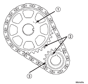
Fig. 61 Crankshaft-Camshaft Alignment
2 - TIMING MARKS
3 - CRANKSHAFT SPROCKET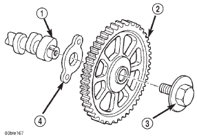
Fig. 62 Camshaft Sprocket and Thrust Plate
2 - CAMSHAFT SPROCKET W/INTEGRAL KEY
3 - BOLT & CUP WASHER
4 - THRUST PLATECamshaft
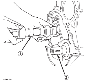
Fig. 63 Camshaft
2 - CRANKSHAFT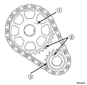
Fig. 64 Crankshaft / Camshaft Sprocket Timing Mark Alignment
2 - TIMING MARKS
3 - CRANKSHAFT SPROCKET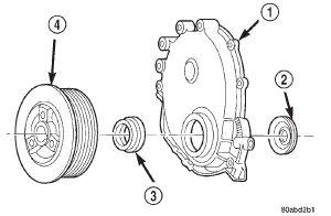
Fig. 65 Timing Case Cover Components
2 - OIL SLINGER
3 - CRANKSHAFT OIL SEAL
4 - VIBRATION DAMPER PULLEYCamshaft bearings
 Hydraulic tappets. Vibration damper. Timing case cover

Other materials:
Cleaning and inspection
TRANSMISSION COMPONENTS
Clean the gears, shafts, shift components and
transmission housings with a standard parts cleaning
solvent. Do not use acid or corrosive base solvents.
Dry all parts except bearings with compressed
air.
Clean the shaft bearings with a mild solvent such
as Mopart de ...