Jeep Cherokee (XJ): Valve timing. Valve, guide and seal. Piston-fitting
Clean all carbon deposits from the combustion
chambers, valve ports, valve stems, valve stem
guides and head.
Clean all grime and gasket material from the
engine cylinder head machined gasket surface.
Inspect for cracks in the combustion chambers and
valve ports.
Inspect for cracks on the exhaust seat.
Inspect for cracks in the gasket surface at each
coolant passage.
Inspect valves for burned, cracked or warped
heads.
Inspect for scuffed or bent valve stems.
Replace valves displaying any damage. VALVE REFACING (1) Use a valve refacing machine to reface the
intake and exhaust valves to the specified angle.
(2) After refacing, a margin of at least 0.787 mm
(0.031 inch) must remain (Fig. 13). If the margin is
less than 0.787 mm (0.031 inch), the valve must be
replaced. VALVE SEAT REFACING (1) Install a pilot of the correct size in the valve
guide bore. Reface the valve seat to the specified
angle with a good dressing stone. Remove only
enough metal to provide a smooth finish.
(2) Use tapered stones to obtain the specified seat
width when required.
(3) Control valve seat runout to a maximum of
0.0635 mm (0.0025 in.)- (Fig. 14). VALVE STEM OIL SEAL REPLACEMENT Valve stem oil seals are installed on each valve
stem to prevent rocker arm lubricating oil from
entering the combustion chamber through the valve
guide bores. One seal is marked INT (intake valve)
and the other is marked EXH (exhaust valve).
Replace the oil seals whenever valve service is performed
or if the seals have deteriorated.
1 - 0.787 MM (1/32 INCH) VALVE MARGIN
1 - DIAL INDICATOR VALVE GUIDES The valve guides are an integral part of the engine
cylinder head and are not replaceable.
When the valve stem guide clearance is excessive,
the valve guide bores must be reamed oversize. Service
valves with oversize stems are available in 0.076
mm (0.003 inch) and 0.381 mm (0.015 inch) increments.
Corresponding oversize valve stem seals are also
available and must be used with valves having 0.381
mm (0.015 inch) oversize stems, 0.076mm (.003in.)
oversize stems do not require oversize seals.
NOTE: If the valve guides are reamed oversize, the
valve seats must be ground to ensure that the valve
seat is concentric to the valve guide. VALVE STEM-TO-GUIDE CLEARANCE
MEASUREMENT Valve stem-to-guide clearance may be measured by
either of the following two methods. PREFERRED METHOD: (1) Remove the valve from the head.
(2) Clean the valve stem guide bore with solvent
and a bristle brush.
(3) Insert a telescoping gauge into the valve stem
guide bore approximately 9.525 mm (.375 inch) from
the valve spring side of the head (Fig. 15).
1 - GAUGE (4) Remove and measure telescoping gauge with a
micrometer.
(5) Repeat the measurement with contacts lengthwise
to engine cylinder head.
(6) Compare the crosswise to lengthwise measurements
to determine out-of-roundness. If the measurements
differ by more than 0.0635 mm (0.0025 in.),
ream the guide bore to accommodate an oversize
valve stem.
(7) Compare the measured valve guide bore diameter
with specifications (7.95-7.97 mm or 0.313-0.314 inch). If the measurement
differs from specification
by more than 0.076 mm (0.003 inch), ream the guide
bore to accommodate an oversize valve stem. ALTERNATIVE METHOD: (1) Use a dial indicator to measure the lateral
movement of the valve stem (stem-to-guide clearance).
This must be done with the valve installed in
its guide and just off the valve seat (Fig. 16).
(2) Correct clearance is 0.025-0.0762 mm
(0.001-0.003 inch). If indicated movement exceeds the
specification ream the valve guide to accommodate
an oversize valve stem.
NOTE: Valve seats must be ground after reaming
the valve guides to ensure that the valve seat is
concentric to the valve guide.
1 - DIAL INDICATOR VALVE SPRING TENSION TEST Use a Universal Valve Spring Tester and a torque
wrench to test each valve spring for the specified tension
value (Fig. 17).
Replace valve springs that are not within specifications. BORE GAUGE METHOD (1) To correctly select the proper size piston, a cylinder
bore gauge, capable of reading in 0.003 mm
(.0001 in.) INCREMENTS is required. If a bore
gauge is not available, do not use an inside micrometer.
1 - TORQUE WRENCH (2) Measure the inside diameter of the cylinder
bore at a point 49.5 mm (1-15/16 inches) below top of
bore. Start perpendicular (across or at 90 degrees) to
the axis of the crankshaft at point A and then take
an additional bore reading 90 degrees to that at point
B (Fig. 19).
(3) The coated pistons will be serviced with the
piston pin and connecting rod pre-assembled. The
coated piston connecting rod assembly can be
used to service previous built engines and
MUST be replaced as complete sets. Tin coated
pistons should not be used as replacements for coated
pistons.
(4) The coating material is applied to the piston
after the final piston machining process. Measuring
the outside diameter of a coated piston will not provide
accurate results (Fig. 18). Therefore measuring
the inside diameter of the cylinder bore with a dial
Bore Gauge is MANDATORY. To correctly select the
proper size piston, a cylinder bore gauge capable of
reading in 0.003 mm (.0001 in.) increments is
required.
(5) Piston installation into the cylinder bore
requires slightly more pressure than that required
for non-coated pistons. The bonded coating on the
piston will give the appearance of a line-to-line fit
with the cylinder bore.
1 - MOLY COATED
1 - FRONT PISTON SIZE CHART
Valve timing
Valve, guide and seal
Fig. 13 Valve Facing Margin
2 - NO MARGIN
Fig. 14 Measurement of Valve Seat Runout
Fig. 15 Measurement of Valve Guide Bore Diameter
2 - 9.525 MM (3/8 INCH)
3 - VALVE STEM GUIDE
4 - CYLINDER HEAD
Fig. 16 Measurement of Lateral Movement Of Valve StemPiston-fitting
Fig. 17 Valve Spring Tester
2 - VALVE SPRING TESTER
Fig. 18 Moly Coated Piston
2 - MOLY COATED
Fig. 19 Bore Gauge
2 - BORE GAUGE
3 - CYLINDER BORE
4 - 49.5 MM
(1-15/16 in)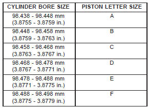


Other materials:
Enabling And Disabling The ParkSense Active Park Assist System. Parallel Parking Space Assistance Operation/Display. Perpendicular Parking Space Assistance Operation/Display
Enabling And Disabling The ParkSense Active Park Assist System
The ParkSense Active Park Assist system can be enabled
and disabled with the ParkSense Active Park Assist
switch, located on the switch panel below the Uconnect
display.
ParkSense Active Park Assist Switch
To enable the ParkSens ...