Jeep Cherokee (XJ): Engine mounts-front. Engine mount-rear. Engine
The front mounts support the engine at each side.
These supports are made of resilient rubber. REMOVAL (1) Disconnect negative cable from battery.
(2) Raise the vehicle.
(3) Support the engine.
(4) Remove through bolt nut (Fig. 42). DO NOT
remove the through bolt.
(5) Remove the retaining bolts and nuts from the
support cushions (Fig. 42).
(6) Remove the through bolt.
(7) Remove the support cushions. INSTALLATION (1) If the engine support bracket was removed,
position the LEFT bracket (Fig. 42) and the RIGHT
bracket (Fig. 43) onto the cylinder block. Install the
bolts and stud nuts.
(a) RIGHT SIDE (Fig. 43) -Tighten the bolts to
61 N·m (45 ft. lbs.) torque. Tighten the stud nuts to
46 N·m (34 ft. lbs.) torque.
(b) LEFT SIDE (Fig. 42) -Tighten the bolts to
61 N·m (45 ft. lbs.) torque.
(2) If the support cushion brackets were removed,
position the brackets onto the lower front sill (Fig.
42) (Fig. 44). Install the bolts and stud nuts. Tighten
the bolts to 54 N·m (40 ft. lbs.) torque and the stud
nuts to 41 N·m (30 ft. lbs.) torque.
1 - ENGINE SUPPORT BRACKET (3) Place the support cushions onto the support
cushion brackets (Fig. 42). Tighten the right support
cushion nuts to 65 N·m (48 ft. lbs.) torque. Tighten
the left support cushion bolt and nut to 41 N·m (30
ft. lbs.) torque.
(4) Install the through bolt and the retaining nut
(Fig. 42). Tighten the through bolt nut to 65 N·m (48
ft. lbs.) torque.
(5) Remove the engine support.
(6) Lower the vehicle.
(7) Connect negative cable to battery. A resilient rubber cushion supports the transmission
at the rear between the transmission extension
housing and the rear support crossmember or skid
plate.
1 - ENGINE SUPPORT BRACKET
1 - LOWER FRONT SILL REMOVAL (1) Disconnect negative cable from battery.
(2) Raise the vehicle and support the transmission.
(3) Remove the nuts holding the support cushion
to the crossmember (Fig. 45) (Fig. 46). Remove the
crossmember. MANUAL TRANSMISSION:
a. Remove the support cushion nuts and remove
the cushion.
b. If necessary, remove the bolts holding the transmission
support bracket to the transmission (Fig. 45).
Remove the bracket.
1 - TRANSMISSION SUPPORT BRACKET AUTOMATIC TRANSMISSION: a. Remove the support cushion bolts and remove
the cushion and the transmission support bracket.
b. If necessary on 2WD vehicles, remove the bolts
holding the transmission support adaptor bracket to
the transmission (Fig. 46). Remove the adaptor
bracket. INSTALLATION MANUAL TRANSMISSION:
a. If removed, position the transmission support
bracket to the transmission and install the bolts.
Tighten the bolts to 43 N·m (32 ft. lbs.) torque.
b. Position the support cushion onto the transmission
support bracket. Install and tighten the nuts to
46 N·m (34 ft. lbs.) torque. AUTOMATIC TRANSMISSION:
a. If removed, position the transmission support
adaptor bracket (2WD vehicles) to the transmission
and install the bolts. Tighten the bolts to 75 N·m (55
ft. lbs.) torque.
b. Position the transmission support bracket and
support cushion to the transmission and install the
bolts. Tighten the bolts to 75 N·m (55 ft. lbs.) torque.
(1) Position the crossmember onto the support
cushion studs and install the nuts. Tighten the nuts
to 22 N·m (192 in. lbs.) torque.
(2) Install the crossmember to sill bolts and
tighten to 41 N·m (30 ft. lbs.) torque.
(3) Remove the transmission support.
(4) Lower the vehicle.
(5) Connect negative cable to battery.
Fig. 46 Rear Mount (Automatic Transmission) 1 - 434 REMOVAL (1) Disconnect the battery cables. Remove the battery.
(2) Mark the hinge locations on the hood panel for
alignment reference during installation. Remove the
engine compartment lamp. Remove the hood.
WARNING: THE COOLANT IN A RECENTLY OPERATED
ENGINE IS HOT AND PRESSURIZED. USE
CARE TO PREVENT SCALDING BY HOT COOLANT.
CAREFULLY RELEASE THE PRESSURE BEFORE
REMOVING THE RADIATOR DRAIN COCK AND CAP.
(3) Loosen the radiator drain cock and radiator cap
to drain the coolant. DO NOT waste usable coolant.
If the solution is clean, drain the coolant into a clean
container for reuse.
(4) Remove the air cleaner assembly (Fig. 47).
(5) Remove the lower radiator hose.
1 - AIR CLEANER ASSEMBLY (6) Remove the upper radiator hose and coolant
recovery hose (Fig. 48).
(7) Remove the fan shroud (Fig. 48).
1 - UPPER RADIATOR HOSE (8) Remove the radiator/condenser (if equipped
with air conditioning).
(9) Remove fan assembly and install a 5/16 x 1/2-
inch SAE capscrew through fan pulley into water
pump flange. This will maintain the pulley and
water pump in alignment when crankshaft is rotated.
(10) Disconnect the heater hoses.
(11) Disconnect the throttle cable, speed control
cable (if equipped) and transmission cable (if
equipped).
(12) Disconnect the body ground at the firewall.
(13) Disconnect the wires from the starter motor
solenoid.
(14) Disconnect all fuel injection harness connections.
WARNING: THE FUEL SYSTEM IS UNDER A CONSTANT
PRESSURE (EVEN WITH THE ENGINE
TURNED OFF). BEFORE DISCONNECTING FUEL
LINES, THE FUEL SYSTEM PRESSURE MUST BE
RELEASED.
(15) Perform fuel pressure release procedure.
(refer to Group 14, Fuel System for the proper procedure).
(16) Remove latch clip and disconnect the quickconnect
fuel line at the fuel rail
(17) Recover refrigerant (if equipped with A/C).
(Refer to group 24, Heating and Air Conditioning for
proper procedures.)
(18) Disconnect suction/discharge hose from A/C
compressor and cap off ports to prevent intrusion of
foreign material or refrigerant oil loss.
(19) Remove the power brake vacuum check valve
from the booster, if equipped.
(20) If equipped with power steering :
(a) Disconnect the power steering hoses from the
fittings at the steering gear.
(b) Drain the pump reservoir.
(c) Cap the fittings on the hoses and steering
gear to prevent foreign material from entering the
system.
(21) Identify, tag and disconnect all necessary wire
connectors and vacuum hoses.
(22) Raise the vehicle.
(23) Remove the oil filter.
(24) Remove the starter motor.
(25) Disconnect the exhaust pipe from the exhaust
manifold.
(26) Remove the flywheel housing access cover.
(27) Remove the upper flywheel and converter
housing bolts and loosen the bottom bolts.
(28) Remove the engine support cushion-to-engine
compartment bracket bolts.
(29) Remove the engine shock damper bracket
from the sill.
(30) Lower the vehicle.
(31) Attach a lifting device to the engine. (32) Raise the engine slightly off the front supports.
(33) Place a support stand under the converter or
flywheel housing.
(34) Lift the engine out of the engine compartment
and install on an engine stand.
(35) Install the oil filter to keep foreign material
out of the engine. INSTALLATION (1) Remove the oil filter.
(2) Lift the engine off the stand and lower it into
the engine compartment. For easier installation, it
may be useful to remove the engine support cushions
from the engine support brackets as an aide for
alignment of the engine-to-transmission.
(3) Insert the transmission shaft into the clutch
spline. (M/T models)
(4) Align the flywheel housing with the engine.
(5) Install and tighten the flywheel housing lower
bolts.
(6) Install the engine support cushions (if
removed).
(7) Lower the engine and engine support cushions
onto the engine compartment brackets.
(8) Remove the engine lifting device.
(9) Raise the vehicle.
(10) Install the converter-housing access cover.
(11) Install the exhaust pipe support.
(12) Install the starter motor and connect the
cable. Tighten the bolts to 45 N·m (33 ft. lbs.) torque.
(13) Tighten the engine support cushion throughbolt
nuts.
(14) Connect the exhaust pipe to the manifold.
(15) Install the oil filter.
(16) Lower the vehicle.
(17) Connect the coolant hoses and tighten the
clamps.
(18) If equipped with power steering:
(a) Remove the protective caps
(b) Connect the hoses to the fittings at the steering
gear. Tighten the nut to 52 N·m (38 ft. lbs.)
torque.
(c) Fill the pump reservoir with fluid.
(19) Remove the pulley-to-water pump flange
alignment capscrew and install the fan assembly.
(20) Install the fan shroud and radiator and condenser
(if equipped with air conditioning).
(21) Connect the radiator hoses.
(22) Connect the oxygen sensor wire connector.
(23) Connect the throttle cable and install the rod.
Connect the transmission and speed control cables (if
equipped)
(24) Connect the fuel supply line to the injector
rail. push until a "click" is heard. Re-install latch
clip.
(25) Connect all the vacuum hoses and wire connectors.
(26) Connect suction/discharge hose to compressor.
(if equipped)
(27) Fill the power steering reservoir.
(28) Connect the battery cables.
(29) Install the air cleaner (Fig. 47).
(30) Install the hood.
(31) Add engine oil and coolant.
(32) Start the engine and inspect for leaks.
(33) Stop the engine and check the fluid levels.
Add fluid, as required.
(34) Recharge air conditioning (Refer to group 24,
Heating and Air Conditioning for proper procedures).Engine mounts-front
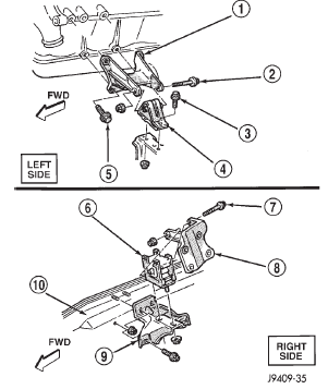
Fig. 42 Front Mounts
2 - THROUGH BOLT
3 - RETAINING BOLT
4 - SUPPORT CUSHION
5 - ATTACHING BOLT
6 - SUPPORT CUSHION
7 - THROUGH BOLT
8 - ENGINE SUPPORT BRACKET
9 - SUPPORT CUSHION BRACKET
10 - SILLEngine mount-rear
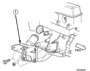
Fig. 43 Engine Support Bracket-Right Side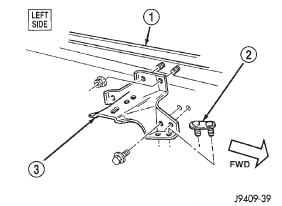
Fig. 44 Support Cushion Bracket-Left Side
2 - TRACK BAR MOUNTING PLATE
3 - SUPPORT CUSHION BRACKET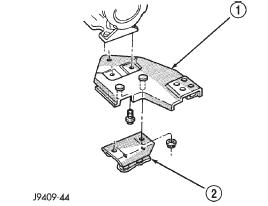
Fig. 45 Rear Mount (Manual Transmission)
2 - SUPPORT CUSHION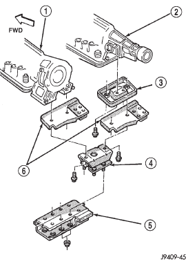
2 - 234
3 - TRANSMISSION SUPPORT ADAPTOR BRACKET
4 - SUPPORT CUSHION
5 - CROSSMEMBER ASSEMBLY
6 - TRANSMISSION SUPPORT BRACKETEngine
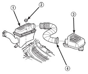
Fig. 47 Air Cleaner and Resonator Removal and Installation
2 - NUT AND WASHER
3 - RESONATOR ASSEMBLY
4 - AIR INLET HOSE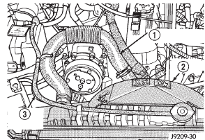
Fig. 48 Upper Radiator Hose, Coolant Recovery Hose & Fan Shroud
2 - FAN SHROUD
3 - COOLANT RECOVERY HOSE


Other materials:
Transmission
CAUTION: The transmission and torque converter
must be removed as an assembly to avoid component
damage. The converter drive plate, pump bushing, or
oil seal can be damaged if the converter is left
attached to the driveplate during removal.
REMOVAL
(1) Disconnect battery negative cable.
(2) ...