Jeep Cherokee (XJ): Fluid. Torque converter. Oil pump
NOTE: Refer to the maintenance schedules in
Group 0, Lubrication and Maintenance for the recommended
maintenance (fluid/filter change) intervals
for this transmission.
NOTE: Refer to Service Procedures in this group
for fluid level checking procedures. DESCRIPTION Mopart Dexron IIE/Mercon is the recommended
fluid for the AW-4 automatic transmissions.
1 - 2ND COAST BRAKE
1 - CLUTCH Dexron II fluid IS NOT recommended. Clutch
chatter can result from the use of improper
fluid.
Mopart Dexron IIE/Mercon automatic transmission
fluid when new is red in color. The ATF is dyed red
so it can be identified from other fluids used in the
vehicle such as engine oil or antifreeze. The red color
is not permanent and is not an indicator of fluid condition.
As the vehicle is driven, the ATF will begin to
look darker in color and may eventually become
brown. This is normal. A dark brown/black fluid
accompanied with a burnt odor and/or deterioration
in shift quality may indicate fluid deterioration or
transmission component failure. FLUID ADDITIVES DaimlerChrysler strongly recommends against the
addition of any fluids to the transmission, other than
those automatic transmission fluids listed above.
Exceptions to this policy are the use of special dyes
to aid in detecting fluid leaks.
Various "special" additives and supplements exist
that claim to improve shift feel and/or quality. These
additives and others also claim to improve converter
clutch operation and inhibit overheating, oxidation,
varnish, and sludge. These claims have not been supported
to the satisfaction of DaimlerChrysler and
these additives must not be used. The use of transmission
"sealers" should also be avoided, since they
may adversely affect the integrity of transmission
seals. OPERATION The automatic transmission fluid is selected based
upon several qualities. The fluid must provide a high
level of protection for the internal components by
providing a lubricating film between adjacent metal
components. The fluid must also be thermally stable
so that it can maintain a consistent viscosity through
a large temperature range. If the viscosity stays constant
through the temperature range of operation,
transmission operation and shift feel will remain consistent.
Transmission fluid must also be a good conductor
of heat. The fluid must absorb heat from the
internal transmission components and transfer that
heat to the transmission case. DESCRIPTION The torque converter (Fig. 5) is a hydraulic device
that couples the engine crankshaft to the transmission.
The torque converter consists of an outer shell
with an internal turbine, a stator, an overrunning
clutch, an impeller and an electronically applied converter
clutch. The converter clutch provides reduced
engine speed and greater fuel economy when
engaged. Clutch engagement also provides reduced
transmission fluid temperatures. Torque converter
clutch engagement occurs in second gear in 1-2 position;
third gear in 3 position and third and fourth
gear in D position. The torque converter hub drives
the transmission oil (fluid) pump.
The torque converter is a sealed, welded unit that
is not repairable and is serviced as an assembly.
CAUTION: The torque converter must be replaced if
a transmission failure resulted in large amounts of
metal or fiber contamination in the fluid. If the fluid
is contaminated, flush the fluid cooler and lines.
1 - TURBINE IMPELLER The impeller (Fig. 6) is an integral part of the converter
housing. The impeller consists of curved vanes
placed radially along the inside of the housing on the
transmission side of the converter. As the converter
housing is rotated by the engine, so is the impeller,
because they are one in the same and are the driving
member of the system.
1 - ENGINE FLEXPLATE TURBINE The turbine (Fig. 7) is the output, or driven, member
of the converter. The turbine is mounted within
the housing opposite the impeller, but is not mounted
to the housing. The input shaft is inserted through
the center of the impeller and splined into the turbine.
The design of the turbine is similar to the
impeller, except the blades of the turbine are curved
in the opposite direction.
1 - TURBINE VANE STATOR The stator assembly (Fig. 8) is mounted on a stationary
shaft which is an integral part of the oil
pump. The stator also contains an over-running
clutch. The stator is located between the impeller
and turbine within the torque converter case (Fig. 9).
The over-running clutch of the stator allows the stator
to rotate only in a clockwise direction.
1 - CAM (OUTER RACE) TORQUE CONVERTER CLUTCH (TCC) The TCC (Fig. 10) was installed to improve the
efficiency of the torque converter that is lost to the
slippage of the fluid coupling. Although the fluid coupling
provides smooth, shock-free power transfer, it
is natural for all fluid couplings to slip. If the impeller
and turbine were mechanically locked together, a
zero slippage condition could be obtained. A hydraulic
piston was added to the turbine, and a friction material
was added to the inside of the impeller housing
to provide this mechanical lock-up. OPERATION The converter impeller (Fig. 11) (driving member),
which is integral to the converter housing and bolted
to the engine drive plate, rotates at engine speed.
The converter turbine (driven member), which reacts
from fluid pressure generated by the impeller, rotates
and turns the transmission input shaft. TURBINE As the fluid that was put into motion by the impeller
blades strikes the blades of the turbine, some of
the energy and rotational force is transferred into the
turbine and the input shaft. This causes both of them (turbine and input shaft)
to rotate in a clockwise
direction following the impeller. As the fluid is leaving
the trailing edges of the turbine's vanes it continues
in a "hindering" direction back toward the
impeller. If the fluid is not redirected before it strikes
the impeller, it will strike the impeller in such a
direction that it would tend to slow it down.
1 - STATOR
1 - IMPELLER FRONT COVER
1 - APPLY PRESSURE STATOR Torque multiplication is achieved by locking the
clutch to its shaft (Fig. 12). Under stall conditions
(the turbine is stationary), the oil leaving the turbine
vanes strikes the face of the stator vanes and tries to
rotate them in a counterclockwise direction. When
this happens the over-running clutch of the stator
locks and holds the stator from rotating. With the
stator locked, the oil strikes the stator vanes and is
redirected into a "helping" direction before it enters
the impeller. This circulation of oil from impeller to
turbine, turbine to stator, and stator to impeller, can
produce a maximum torque multiplication of about
2.2:1. As the turbine begins to match the speed of the
impeller, the fluid that was hitting the stator in such
as way as to cause it to lock-up is no longer doing so.
In this condition of operation, the stator begins to
free wheel and the converter acts as a fluid coupling.
1 - DIRECTION STATOR WILL FREE WHEEL DUE TO OIL
PUSHING ON BACKSIDE OF VANES TORQUE CONVERTER CLUTCH (TCC) In a standard torque converter, the impeller and
turbine are rotating at about the same speed and the
stator is freewheeling, providing no torque multiplication.
By applying the turbine's piston to the impeller's
friction material, a total converter engagement
can be obtained. The result of this engagement is a
direct 1:1 mechanical link between the engine and
the transmission.
The engagement and disengagement of the TCC
are automatic and controlled by the Transmission
Control Module (TCM). Inputs that determine clutch
engagement are: coolant temperature, vehicle speed
and throttle position. Clutch engagement is controlled
by transmission valve body solenoid number
three and by the converter clutch relay valve. The
solenoid channels line pressure to the clutch through
the relay valve at clutch engagement speeds. DESCRIPTION The oil pump (Fig. 13) is located in the pump housing
inside the bell housing of the transmission case.
The oil pump consists of an inner and outer gear, a
housing, and a cover that also serves as the reaction
shaft support. OPERATION As the torque converter rotates, the converter hub
rotates the inner and outer gears. As the gears
rotate, the clearance between the gear teeth
increases in the crescent area, and creates a suction
at the inlet side of the pump. This suction draws
fluid through the pump inlet from the oil pan. As the
clearance between the gear teeth in the crescent area
decreases, it forces pressurized fluid into the pump
outlet and to the valve body.
1 - PUMP SEALFluid
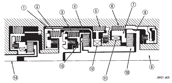
Fig. 3 First/Second/Third/Reverse Gear Components
2 - DIRECT CLUTCH
3 - FORWARD CLUTCH
4 - FRONT PLANETARY RING GEAR
5 - SECOND BRAKE
6 - FIRST/REVERSE BRAKE
7 - REAR PLANETARY CARRIER
8 - REAR PLANETARY RING GEAR
9 - OUTPUT SHAFT
10 - FRONT & REAR PLANETARY SUN GEAR
11 - ONE-WAY CLUTCH NO. 2
12 - ONE-WAY CLUTCH NO. 1
13 - FRONT PLANETARY CARRIER
14 - INPUT SHAFT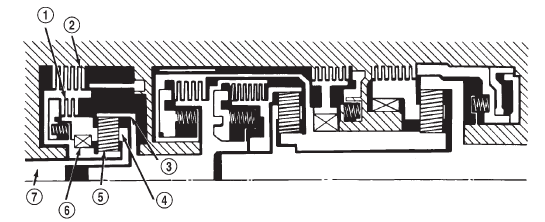
Fig. 4 Fourth Gear Overdrive Components
2 - BRAKE
3 - RING GEAR
4 - PLANETARY CARRIER
5 - SUN GEAR
6 - ONE-WAY CLUTCH
7 - INPUT SHAFTTorque converter
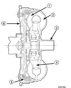
Fig. 5 Torque Converter Assembly
2 - IMPELLER
3 - HUB
4 - STATOR
5 - CONVERTER CLUTCH DISC
6 - DRIVE PLATE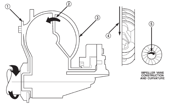
Fig. 6 Impeller
2 - OIL FLOW FROM IMPELLER SECTION INTO TURBINE
SECTION
3 - IMPELLER VANES AND COVER ARE INTEGRAL
4 - ENGINE ROTATION
5 - ENGINE ROTATION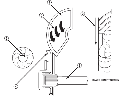
Fig. 7 Turbine
2 - ENGINE ROTATION
3 - INPUT SHAFT
4 - PORTION OF TORQUE CONVERTER COVER
5 - ENGINE ROTATION
6 - OIL FLOW WITHIN TURBINE SECTION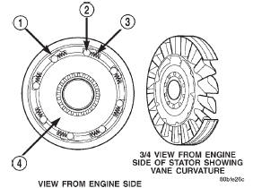
Fig. 8 Stator Components
2 - ROLLER
3 - SPRING
4 - INNER RACE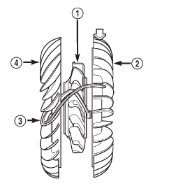
Fig. 9 Stator Location
2 - IMPELLER
3 - FLUID FLOW
4 - TURBINE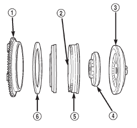
Fig. 10 Torque Converter Clutch (TCC)
2 - THRUST WASHER ASSEMBLY
3 - IMPELLER
4 - STATOR
5 - TURBINE
6 - FRICTION DISC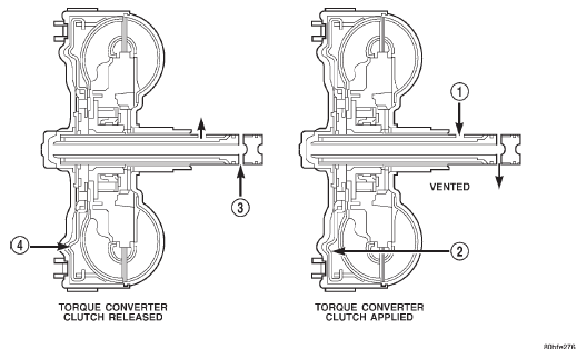
Fig. 11 Torque Converter Fluid Operation
2 - THE PISTON MOVES SLIGHTLY FORWARD
3 - RELEASE PRESSURE
4 - THE PISTON MOVES SLIGHTLY REARWARD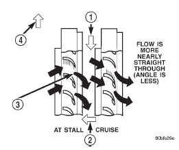
Fig. 12 Stator Operation
2 - FRONT OF ENGINE
3 - INCREASED ANGLE AS OIL STRIKES VANES
4 - DIRECTION STATOR IS LOCKED UP DUE TO OIL PUSHING
AGAINST STATOR VANESOil pump
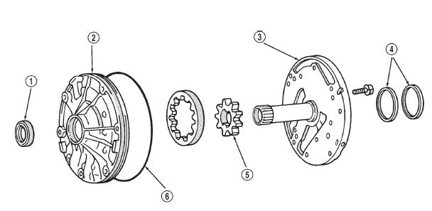
Fig. 13 Oil Pump Assembly
2 - PUMP BODY
3 - STATOR SHAFT
4 - SEAL RINGS
5 - GEAR
6 - O-RING

 Transmission valve body components
Other materials:
Hazard warning flashers
The hazard warning flasher switch is located in the
switch bank below the radio screen.
Push the switch to turn on the
Hazard Warning
flasher. When the switch is activated, all directional
turn signals will flash on and off to warn oncoming
traffic of an emergency. Push the switch a second ti ...