Jeep Cherokee (XJ): Front door trim panel. Front door waterdam. Front door
REMOVAL (1) Roll window down.
(2) Remove window crank, if equipped (Fig. 21).
(3) Remove the screws attaching the trim panel to
the door inner panel (Fig. 22) and (Fig. 23).
(4) Separate the trim panel fasteners from door
inner panel with a pry tool (use special tool C-4829)
(Fig. 24).
(5) Lift the trim panel up and outward to separate
from the inner belt seal.
(6) Move the door trim panel outward and disconnect
the handle-to-latch rods.
(7) Disconnect the power door locks/windows/mirrors
wire harness connectors, if equipped.
(8) Remove the trim panel from door. INSTALLATION (1) Replace any broken or damaged push-in fasteners.
(2) Connect the power door locks/windows/mirrors
wire harness connectors, if equipped.
(3) Move the door trim panel outward and connect
the handle-to-latch rods.
(4) Position the trim panel on the inner belt seal
and push down to seat.
(5) Align the locating pins and push- (Fig. 25) in
fasteners. Press inward to secure.
(6) Install the screws attaching the trim panel to
the door inner panel.
(7) Install the window crank, if equipped.
1 - WINDOW CRANK REMOVAL TOOL
1 - U-NUT REMOVAL The waterdam is attached to the door inner panel
with a butly adhesive. If cohesive separation of the
butly between the waterdam and door inner panel
occurs during the removal process, cut the strands of
butly with a razor knife or equivalent.
(1) Remove door trim panel.
(2) Disengage clips attaching wire harnesses to the
door inner panel.
(3) Push the harnesses/connectors through the
waterdam and into the door.
1 - U-NUT
(4) Grasp the upper and lower rearward corners of
the waterdam and rapidly peel back the waterdam
from the door inner panel.
(5) Separate the waterdam from the door inner
panel. INSTALLATION (1) Route the latch rods through the waterdam.
(2) Position the waterdam on the door, apply adhesive
as necessary and press into place.
(3) Route the harnesses/connectors through the
waterdam.
1 - LOCATING PINS (4) Engage clips attaching wire harnesses to the
door inner panel.
(5) Install door trim panel. REMOVAL (1) Remove door restraint (check) retaining pin.
(2) For vehicles equipped with power windows,
power mirrors and power door locks, remove trim
panel and waterdam. Disconnect all components and
route wire harness out of door.
(3) Remove bolts that attach hinge to door (Fig.
26).
(4) Remove door from vehicle. INSTALLATION (1) Position door in body opening.
(2) Align door hinges, plates and shims and install
bolts. Tighten bolts to 3 N·m (2 ft. lbs.) torque.
(3) Install door restraint (check) pin.
(4) If applicable, route and connect wire harness
connectors.
(5) Install door waterdam and trim panel.Front door trim panel
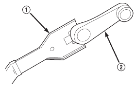
Fig. 21 Window Crank-Typical
2 - WINDOW CRANK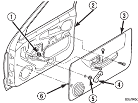
Fig. 22 Front Door Trim Panel-Manual Window
2 - DOOR
3 - TRIM PANEL
4 - WINDOW CRANK
5 - SPACER
6 - PUSH-IN FASTENERFront door waterdam
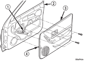
Fig. 23 Front Door Trim Panel-Power Window
2 - DOOR
3 - TRIM PANEL
4 - PUSH-IN FASTENER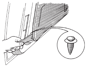
Fig. 24 Detaching Trim Panel Push-In Fasteners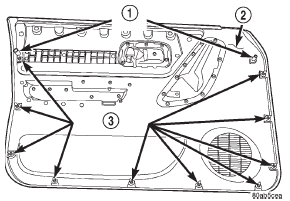
Fig. 25 Push-In Fasteners
2 - TRIM PANEL
3 - PUSH-IN FASTENERSFront door
 Front wheelhouse liner. Right front fender. Left front fender
 Front door hinge. Front door restraint. Front door outside handle
Other materials:
Fuel pump relay-pcm output. Idle air control (iac) motor-pcm
output. Radiator fan relay-pcm output
Fuel pump relay-pcm output
DESCRIPTION
The 5-pin, 12-volt, fuel pump relay is located in
the Power Distribution Center (PDC). Refer to the
label on the PDC cover for relay location.
OPERATION
The Powertrain Control Module (PCM) energizes
the electric fuel pump through the fuel pump relay.
T ...
