Jeep Cherokee (XJ): Gearshift cable. Brake transmission shift interlock. Valve body
REMOVAL (1) Shift transmission into Park.
(2) Remove shift lever bezel and necessary console
parts for access to shift lever assembly.
(3) Disconnect cable at shift lever and feed cable
through dash panel opening to underside of vehicle.
(4) Raise vehicle.
(5) Disengage cable eyelet at transmission shift
lever and pull cable adjuster out of mounting
bracket. Then remove old cable from vehicle. INSTALLATION (1) Route cable through hole in dash panel. Fully
seat cable grommet into dash panel.
(2) Place the auto transmission manual shift control
lever in "Park" detent (rearmost) position and
rotate prop shaft to ensure transmission is in park.
(3) Connect shift cable to shifter mechanism by
snapping cable retaining ears into shifter bracket
and press cable end fitting onto lever ball stud.
(4) Place the floor shifter lever in park position.
Ensure that the pawl is seated within the confines of
the adjustment gauge clip.
(5) Snap the cable into the transmission bracket so
the retaining ears are engaged and connect cable end
fitting onto the manual control lever ball stud.
(6) Lock shift cable into position by pushing
upward on the adjusting lock button.
(7) Remove and discard the shift cable adjustment
gauge clip from the park gate of the shifter. REMOVAL (1) Remove lower steering column cover. Refer to
Group 8E, Instrument Panel and Gauges, for proper
procedure.
(2) Remove lower steering column shroud. Refer to
Group 19, Steering, for proper procedure.
(3) Remove tie strap near the solenoid retaining
the brake transmission interlock cable to the steering
column.
(4) Disengage wire connector from solenoid.
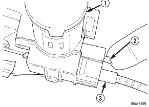
(5) With the ignition removed or in the unlocked
position, disengage lock tab holding cable end to
steering column (Fig. 79).
(6) Pull cable end from steering column.
(7) Remove the floor console and related trim.
Refer to Group 23, Body, for proper procedure.
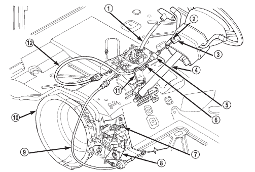
(8) Disconnect the cable eyelet from the bellcrank
(Fig. 80).
1 - IGNITION LOCK (9) Disconnect and remove the cable from the shift
bracket.
1 - SHIFT MECHANISM INSTALLATION (1) Route replacement cable behind instrument
panel and under floor console area to shift mechanism
(Fig. 80).
(2) Insert cable end into opening in steering column
hub under ignition lock. Push cable inward
until lock tab engages.
(3) Connect the cable end eyelet onto shifter
bellcrank pin.
(4) Place gear selector in PARK.
(5) Push the spring-loaded cable adjuster forward
and snap cable into bracket.
(6) Adjust the brake transmission shifter interlock
cable. Refer to the Adjustment portion of this section
for proper procedures.
(7) Verify that the cable adjuster lock clamp is
pushed downward to the locked position.
(8) Test the park-lock cable operation.
(9) Install the floor console and related trim.
(10) Install tie strap to hold cable to base of steering
column.
(11) Install lower steering column shroud and ignition
lock.
(12) Install lower steering column cover. REMOVAL (1) Raise vehicle.
(2) Remove oil pan and drain fluid.
(3) Loosen clamp bolts and remove throttle and
manual valve levers from manual lever shaft.
(4) Remove park/neutral position switch.
(5) Remove filter from valve body.
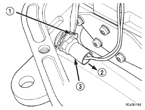
(6) Depress retaining clip and pull solenoid wire
from case connector (Fig. 81).
(7) Remove valve body attaching screws.
(8) Lower valve body enough to remove accumulator
piston and piston spring (Fig. 82).
1 - PUSH CLIP IN (9) Pull valve body forward to disengage park rod.
(10) Push manual lever shaft and solenoid case
connector out of transmission case.
(11) Lower valve body, rotate it away from case,
pull park lock rod out of sprag, and remove valve
body (Fig. 83).
1 - ACCUMULATOR PISTON INSTALLATION (1) Verify that park/neutral position switch is NOT
installed. Valve body cannot be installed with switch
in place. Remove switch if necessary.
(2) Install new seals on accumulator piston if necessary,
and install piston in case. Use small amount
of petroleum jelly to hold piston in place.
(3) Place valve body manual lever in low (1 position)
to ease inserting park rod into sprag.
1 - VALVE BODY (4) Use screwdriver to push park sprag into
engagement with park gear. This makes clearance for
knob on lock rod to move past sprag when valve body
is installed. Rotate output shaft to verify sprag
engagement.
(5) Position accumulator spring between accumulator
piston and valve body.
(6) Position valve body on transmission and work
knob on park lock rod past sprag. Be sure accumulator
piston and spring remain in position.
(7) Hold valve body in position and install valve
body screws finger tight.
(8) Install park/neutral position switch.
(9) Tighten valve body screws alternately and
evenly to 11 N·m (100 in. lbs.) torque.
(10) Install new fluid filter on valve body. Install
and tighten filter screws to 4 N·m (35 in. lbs.) torque.
(11) Connect solenoid wire to case connector.
(12) Install manual and throttle levers on throttle
lever shaft. Tighten lever clamp screws and check for
free operation. Shaft and levers must operate freely
without any bind.
(13) Install oil pan and new gasket. Tighten pan
bolts to 17 N·m (150 in. lbs.) torque. Install gasket
dry; do not use sealer.
(14) Connect park/neutral position switch and converter
clutch solenoid wires.
(15) Install speedometer pinion gear, adapter and
speed sensor.
(16) Lower vehicle. (17) Fill transmission with Mopart ATF Plus 3,
Type 7176 fluid.
(18) Adjust gearshift and throttle cable if necessary.Gearshift cable
Brake transmission shift interlock

Fig. 79 Brake/Park Interlock Cable
2 - LOCK TAB
3 - CABLE END
Fig. 80 Cable and Shifter
2 - LOCK-TAB
3 - IGNITION LOCK INTERLOCK
4 - STEERING COLUMN
5 - SOLENOID
6 - WIRE CONNECTOR
7 - LEVER
8 - MOUNT BRACKET
9 - SHIFT CABLE
10 - AUTOMATIC TRANSMISSION
11 - TIE STRAP
12 - PARK/BRAKE INTERLOCK CABLEValve body

Fig. 81 Solenoid Wire Connector
2 - PULL
3 - CONVERTER CLUTCH SOLENOID CONNECTOR
Fig. 82 Accumulator Piston And Springs
2 - OUTER SPRING
3 - PISTON SEAL RINGS
4 - INNER SPRING (32RH)
Fig. 83 Valve Body
2 - CONVERTER CLUTCH MODULE
3 - SOLENOID
4 - PARK ROD
5 - CONVERTER CLUTCH SOLENOID CONNECTOR
6 - MANUAL VALVE
7 - MANUAL LEVER
 Adapter housing. Speedometer adapter. Park/neutral position switch
 Output shaft rear bearing. Governor and park gear. Park lock
Other materials:
Heater and air conditioner. Heater and air conditioner control. Heater core
Heater and air conditioner
DESCRIPTION
All vehicles are equipped with a common heater-
A/C housing assembly (Fig. 4). The system combines
air conditioning, heating, and ventilating capabilities
in a single unit housing mounted under the instrument
panel. On heater-only systems, the evaporator
...
