Jeep Cherokee (XJ): Heater-A/C housing door
WARNING: ON VEHICLES EQUIPPED WITH AIRBAGS, REFER TO GROUP 8M - PASSIVE RESTRAINT SYSTEMS BEFORE ATTEMPTING ANY STEERING WHEEL, STEERING COLUMN, OR INSTRUMENT PANEL COMPONENT DIAGNOSIS OR SERVICE. FAILURE TO TAKE THE PROPER PRECAUTIONS COULD RESULT IN ACCIDENTAL AIRBAG DEPLOYMENT AND POSSIBLE PERSONAL INJURY.
BLEND-AIR DOOR
(1) Remove and disassemble the heater-A/C housing.
See Heater-A/C Housing in this group for the procedures.
(2) Lift the blend-air door pivot shaft out of the pivot hole in the bottom of the lower half of the heater- A/C housing (Fig. 43).
(3) Reverse the removal procedures to install.
PANEL/DEMIST DOOR AND LEVER
(1) Remove and disassemble the heater-A/C housing.
See Heater-A/C Housing in this group for the procedures.
(2) Remove the defrost and panel/demist door vacuum actuators from the heater-A/C housing. See Mode Door Vacuum Actuator in this group for the procedures.
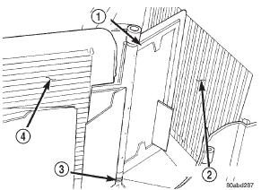
Fig. 43 Blend-Air Door
1 - BLEND-AIR DOOR
2 - EVAPORATOR COIL
3 - PIVOT HOLE
4 - HEATER CORE
(3) Insert a screwdriver into the latch hole (Fig.
44) of the panel/demist door pivot shaft to release the latch of the panel/demist door lever, and pull the lever out of the pivot shaft from the outside of the upper half of the heater-A/C housing.
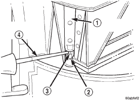
Fig. 44 Mode Door Lever Remove/Install - Typical
1 - DOOR PIVOT SHAFT
2 - LATCH HOLE
3 - CRANK ARM LATCH
4 - FLAT BLADE PRY TOOL
(4) Reach inside the upper half of the heater-A/C housing and carefully flex the panel/defrost door (Fig.
45) enough so that the door pivot clears the pivot hole in the housing.
(5) Remove the panel/demist door from the heater- A/C housing.
(6) Reverse the removal procedures to install.
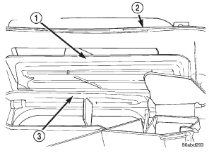
Fig. 45 Panel/Demist and Defrost Doors
1 - PANEL/DEMIST DOOR
2 - UPPER HEATER-A/C HOUSING
3 - DEFROST DOOR
DEFROST DOOR AND LEVER
(1) Remove and disassemble the heater-A/C housing.
See Heater-A/C Housing in this group for the procedures.
(2) Remove the panel/demist door and lever from the upper heater-A/C housing. See Panel/Demist Door and Lever in this group for the procedures.
(3) Insert a screwdriver into the latch hole (Fig.
44) of the defrost door pivot shaft to release the latch of the defrost door lever, and pull the lever out of the pivot shaft from the outside of the upper half of the heater-A/C housing.
(4) Reach inside the upper half of the heater-A/C housing and carefully flex the defrost door (Fig. 45) enough so that the door pivot clears the pivot hole in the housing.
(5) Remove the defrost door from the heater-A/C housing.
(6) Reverse the removal procedures to install.
FLOOR DOOR AND LEVER
(1) Remove and disassemble the heater-A/C housing.
See Heater-A/C Housing in this group for the procedures.
(2) Remove the floor door vacuum actuator from the lower heater-A/C housing. See Mode Door Vacuum Actuator in this group for the procedures.
(3) Insert a screwdriver into the latch hole (Fig.
44) of the floor door pivot shaft to release the latch of the floor door lever, and pull the lever out of the pivot shaft from the outside of the lower half of the heater-A/C housing.
(4) Reach inside the lower half of the heater-A/C housing and carefully flex the floor door (Fig. 46) enough so that the door pivot clears the pivot hole in the housing.
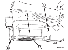
Fig. 46 Floor Door
1 - LOWER HEATER-A/C HOUSING
2 - PIVOT SHAFT
3 - CRANK ARM
4 - FLOOR DOOR
(5) Remove the floor door from the heater-A/C housing.
(6) Reverse the removal procedures to install.
RECIRCULATION AIR DOOR
A recirculation air door and vacuum actuator are used only on models with the optional air conditioning system.
(1) Remove and disassemble the heater-A/C housing.
See Heater-A/C Housing in this group for the procedures.
(2) Remove the recirculation air door vacuum actuator from the lower heater-A/C housing. See Mode Door Vacuum Actuator in this group for the procedures.
(3) Reach inside the lower half of the heater-A/C housing and lift the bottom edge of the recirculation air door upwards (Fig. 47).
(4) Guide the recirculation air door lever through the air intake grille of the heater-A/C housing while removing the door from the housing.
(5) Reverse the removal procedures to install.
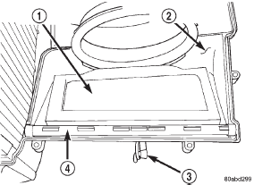
Fig. 47 Recirculation Air Door
1 - RECIRCULATION AIR DOOR
2 - LOWER HEATER-A/C HOUSING
3 - LEVER
4 - PIVOT SHAFT
 Heater core. Liquid line. Low pressure cycling clutch switch
Other materials:
Cleaning and inspection
Caliper
CLEANING
Clean the caliper components with clean brake
fluid or brake clean only. Wipe the caliper and piston
dry with lint free towels or use low pressure compressed
air.
CAUTION: Do not use gasoline, kerosene, thinner,
or similar solvents. These products may leave a
residue that cou ...

