Jeep Cherokee (XJ): Oil pump. Piston and connecting rod. Rear main oil seal
The positive-displacement gear-type oil pump is
driven by the distributor shaft, which is driven by a
gear on the camshaft. Oil is siphoned into the pump through an inlet tube and
strainer assembly that is
pressed into the pump body.
The pump incorporates a nonadjustable pressure
relief valve to limit maximum pressure to 517 kPa
(75 psi). In the relief position, the valve permits oil to
bypass through a passage in the pump body to the
inlet side of the pump.
Oil pump removal or replacement will not affect
the distributor timing because the distributor drive
gear remains in mesh with the camshaft gear. REMOVAL (1) Drain the engine oil.
(2) Remove the oil pan.
(3) Remove the pump-to-cylinder block attaching
bolts. Remove the pump assembly with gasket (Fig.
84).
CAUTION: If the oil pump is not to be serviced, DO
NOT disturb position of oil inlet tube and strainer
assembly in pump body. If the tube is moved within
the pump body, a replacement tube and strainer
assembly must be installed to assure an airtight
seal.
1 - OIL FILTER ADAPTOR INSTALLATION (1) Install the oil pump on the cylinder block using
a replacement gasket. Tighten the bolts to 23 N·m
(17 ft. lbs.) torque.
(2) Install the oil pan and gasket.
(3) Fill the oil pan with oil to the specified level. REMOVAL (1) Remove the engine cylinder head cover.
(2) Remove the rocker arms, bridges and pivots.
(3) Remove the push rods.
(4) Remove the engine cylinder head.
(5) Position the pistons one at a time near the bottom
of the stroke. Use a ridge reamer to remove the
ridge from the top end of the cylinder walls. Use a
protective cloth to collect the cuttings.
(6) Raise the vehicle.
(7) Drain the engine oil.
(8) Remove the oil pan and gasket.
(9) Remove the connecting rod bearing caps and
inserts. Mark the caps and rods with the cylinder
bore location. The connecting rods and caps are
stamped with a two letter combination (Fig. 85).
1 - CONNECTING ROD CAP (10) Lower the vehicle until it is about 2 feet from
the floor.
CAUTION: Ensure that the connecting rod bolts DO
NOT scratch the crankshaft journals or cylinder
walls. Short pieces of rubber hose, slipped over the
rod bolts will provide protection during removal.
(11) Have an assistant push the piston and connecting
rod assemblies up and through the top of the
cylinder bores (Fig. 86).
1 - PISTON INSTALLATION (1) Clean the cylinder bores thoroughly. Apply a
light film of clean engine oil to the bores with a clean
lint-free cloth.
(2) Install the piston rings on the pistons if
removed.
(3) Lubricate the piston and rings with clean
engine oil.
CAUTION: Ensure that connecting rod bolts do not
scratch the crankshaft journals or cylinder walls.
Short pieces of rubber hose slipped over the connecting
rod bolts will provide protection during
installation.
(5) Use a piston ring compressor to install the connecting
rod and piston assemblies through the top of
the cylinder bores (Fig. 87).
(6) Ensure the arrow on the piston top points to
the front of the engine (Fig. 87).
(7) Raise the vehicle.
(8) Each bearing insert is fitted to its respective
journal to obtain the specified clearance between the
bearing and the journal. In production, the select fit
is obtained by using various-sized, color-coded bearing
inserts as listed in the Connecting Rod Bearing
Fitting Chart. The color code appears on the edge of
the bearing insert. The size is not stamped on inserts
used for production of engines.
(9) The rod journal is identified during the engine
production by a color-coded paint mark on the adjacent
cheek or counterweight toward the flange (rear)
end of the crankshaft. The color codes used to indicate
journal sizes are listed in the Connecting Rod
Bearing Fitting Chart.
(10) When required, upper and lower bearing
inserts of different sizes may be used as a pair (refer
to Connecting Rod Bearing Fitting Chart). A standard
size insert is sometimes used in combination
with a 0.025 mm (0.001 inch) undersize insert to
reduce clearance 0.013 mm (0.0005 inch).
CAUTION: DO NOT intermix bearing caps. Each
connecting rod and bearing cap are stamped with
the cylinder number. The stamp is located on a
machined surface adjacent to the oil squirt hole
that faces the camshaft side of the cylinder block.
(11) Install the connecting rod bearing caps and
inserts in the same positions as removed.
CAUTION: Verify that the oil squirt holes in the
rods face the camshaft and that the arrows on the
pistons face the front of the engine.
(13) Install the oil pan and gaskets as outlined in
the installation procedure.
(14) Lower the vehicle.
(15) Install the engine cylinder head, push rods,
rocker arms, bridges, pivots and engine cylinder head
cover.
(16) Fill the crankcase with engine oil. REMOVAL (1) Remove the flywheel or converter drive plate.
Discard the old bolts. (2) Pry out the seal from around the crankshaft
flange, making sure not to scratch or nick the crankshaft.
(Fig. 88).
1 - CRANKSHAFT INSTALLATION (1) Wipe the seal surface area of the crankshaft
until it is clean.
(2) Coat the outer lip of the replacement rear main
bearing seal with engine oil.
(3) Carefully position the seal into place. Use rear
main Seal Installer Tool 6271A to install the seal
flush with the cylinder block.
CAUTION: The felt lip must be located inside the
flywheel mounting surface. If the lip is not positioned
correctly the flywheel could tear the seal.
(4) Install the flywheel or converter drive plate.
New bolts MUST be used when installing the flywheel
or converter plate. Tighten the new bolts to 68
N·m (50 ft. lbs.) torque. Turn the bolts an additional
60.Oil pump
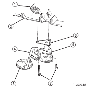
Fig. 84 Oil Pump Assembly
2 - BLOCK
3 - GASKET
4 - OIL INLET TUBE
5 - OIL PUMP
6 - STRAINER ASSEMBLY
7 - ATTACHING BOLTSPiston and connecting rod
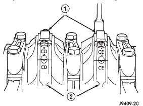
Fig. 85 Stamped Connecting Rods and Caps
2 - CONNECTING ROD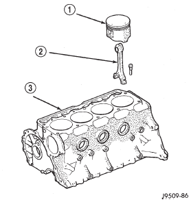
Fig. 86 Removal of Connecting Rod and Piston Assembly
2 - CONNECTING ROD
3 - CYLINDER BLOCK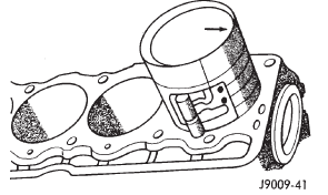
Fig. 87 Rod and Piston Assembly InstallationRear main oil seal
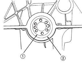
Fig. 88 Replacement of Rear Crankshaft Oil Seal
2 - CRANKSHAFT OIL SEAL
 Camshaft bearings. Crankshaft main bearings. Oil pan
 Disassembly and assembly. Cleaning and inspection. Specifications
Other materials:
Specifications. Special tools
Specifications
TORQUE CHART
DESCRIPTION TORQUE
Air Cleaner Housing Mount. Bolts . . . . . . . . 8 N·m
(71 in. lbs.)
Engine Coolant Temperature Sensor . . . . . . 11 N·m
(96 in. lbs.)
IAC Motor-To-Throttle Body Bolts . . . . . . . . 7 N·m
(60 in. lbs.)
Intake Manifold Air Temp. Sensor . . ...
