Jeep Cherokee (XJ): Semi-synchronized reverse idler gear
DISASSEMBLY
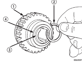
(1) Remove snap-ring holding the reverse idler gear onto the reverse idler gear hub/race (Fig. 115).
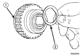
(2) Remove the plate washer from the reverse idler gear hub/race (Fig. 116).

Fig. 115 Remove Reverse Idler Gear Snap-ring
1 - REVERSE IDLER GEAR
2 - SNAP-RING
3 - REVERSE IDLER GEAR HUB
4 - PLATE WASHER

Fig. 116 Remove Reverse Idler Gear Plate Washer
1 - REVERSE IDLER GEAR
2 - PLATE WASHER
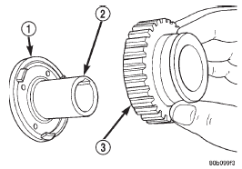
(3) Remove the reverse idler gear from the reverse idler gear hub/race (Fig. 117).
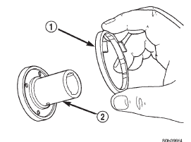
(4) Remove the reverse idler gear synchronizer ring from the reverse idler gear hub/race (Fig. 118).

Fig. 117 Remove Reverse Idler Gear
1 - REVERSE SYNCHRONIZER RING
2 - REVERSE IDLER GEAR HUB
3 - REVERSE IDLER GEAR

Fig. 118 Remove Reverse Idler Gear Synchronizer Ring
1 - REVERSE SYNCHRONIZER RING
2 - REVERSE IDLER GEAR HUB
ASSEMBLY
(1) Install the reverse idler gear synchronizer ring onto the reverse idler gear hub/race. Apply a film of 75W-90 GL-3 transmission oil to the contact surface of the synchronizer ring prior to assembly.
(2) Install the reverse idler gear onto the reverse idler gear hub/race. Apply a film of 75W-90 GL-3 transmission oil to the reverse idler gear bushing prior to assembly. Verify that the teeth on the synchronizer ring are properly engaged into the recesses of the reverse idler gear.
(3) Install the plate washer over the reverse idler gear hub/race and onto the reverse idler gear.
(4) Install the snap-ring to hold the reerse idler gear onto the reverse idler hub/race.
1 - OUTPUT SHAFT FLANGE
2 - INNER RACE FLANGE
1 - OUTPUT SHAFT JOURNAL
COUNTERSHAFT
Inspect the countershaft gear teeth. Replace the countershaft if any teeth are worn or damaged.
Inspect the bearing surfaces and replace shaft if any surface shows damage or wear.
Check condition of the countershaft front bearing.
Replace the bearing if worn, noisy, or damaged.
GEAR AND SYNCHRONIZER
Install the needle bearing and inner race in the first gear. Then check oil clearance between the gear and inner race (Fig. 121). Clearance should be 0.009 - 0.032 mm (0.0004 - 0.0013 in.).
 Countershaft. Input shaft. Output shaft
Other materials:
Engine compartment
ENGINE COMPARTMENT - 2.4L
1 - Air Cleaner Filter
2 - Engine Coolant Pressure Cap
3 - Oil Fill Cap
4 - Brake Fluid Reservoir
5 - Power Distribution Center (Fuses)
6 - Battery
7 - Washer Fluid Reservoir
8 - Engine Oil Dipstick
ENGINE COMPARTMENT - 3.2L
1 - Engine Coolant Reservoir
2 ...

