Jeep Cherokee (XJ): Service procedures
Always clean the master cylinder reservoir and cap
before adding fluid. This will prevent dirt from falling
in the reservoir and contaminating the brake
fluid.
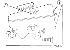
The reservoir has a ADD and a FULL mark on the
side (Fig. 11) fill to the FULL mark.
1 - FLUID LEVEL MARKS A new master cylinder should be bled before installation
on the vehicle. Required bleeding tools include
bleed tubes and a wood dowel to stroke the pistons.
Bleed tubes can be fabricated from brake line. BLEEDING PROCEDURE (1) Mount master cylinder in vise.
(2) Attach bleed tubes to cylinder outlet ports.
Then position each tube end into reservoir (Fig. 12). (3) Fill reservoir with fresh brake fluid.
(4) Press cylinder pistons inward with wood dowel.
Then release pistons and allow them to return under
spring pressure. Continue bleeding operations until
air bubbles are no longer visible in fluid.
1 - BLEEDING TUBES Use Mopar brake fluid, or an equivalent quality
fluid meeting SAE J1703-F and DOT 3 standards
only. Use fresh, clean fluid from a sealed container at
all times.
Do not pump the brake pedal at any time while
bleeding. Air in the system will be compressed into
small bubbles that are distributed throughout the
hydraulic system. This will make additional bleeding
operations necessary.
Do not allow the master cylinder to run out of fluid
during bleed operations. An empty cylinder will allow
additional air to be drawn into the system. Check the
cylinder fluid level frequently and add fluid as
needed.
Bleed only one brake component at a time in the
following sequence: MANUAL BLEEDING (1) Remove reservoir filler caps and fill reservoir.
(2) If calipers, or wheel cylinders were overhauled,
open all caliper and wheel cylinder bleed screws.
Then close each bleed screw as fluid starts to drip
from it. Top off master cylinder reservoir once more
before proceeding.
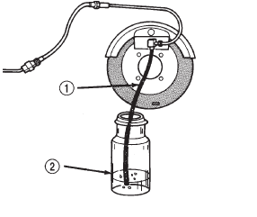
(3) Attach one end of bleed hose to bleed screw
and insert opposite end in glass container partially
filled with brake fluid (Fig. 13). Be sure end of bleed
hose is immersed in fluid.
1 - BLEED HOSE (4) Open up bleeder, then have a helper press
down the brake pedal. Once the pedal is down close
the bleeder. Repeat bleeding until fluid stream is
clear and free of bubbles. Then move to the next
wheel. PRESSURE BLEEDING Follow the manufacturers instructions carefully
when using pressure equipment. Do not exceed the
tank manufacturers pressure recommendations. Generally,
a tank pressure of 15-20 psi is sufficient for
bleeding.
Fill the bleeder tank with recommended fluid and
purge air from the tank lines before bleeding.
Do not pressure bleed without a proper master cylinder
adapter. The wrong adapter can lead to leakage,
or drawing air back into the system. Use
adapter provided with the equipment or Adapter
6921. The disc brake rotor can be machined if scored or
worn. The lathe must machine both sides of the rotor
simultaneously with dual cutter heads. The rotor
mounting surface must be clean before placing on the
lathe. Equipment capable of machining only one side
at a time may produce a tapered rotor. A hub mounted on-vehicle lathe is
recommended. This type
of lathe trues the rotor to the vehicles hub/bearing.
CAUTION: Brake rotors that do not meet minimum
thickness specifications before or after machining
must be replaced. The brake drums can be machined on a drum lathe
when necessary. Initial machining cuts should be limited
to 0.12 - 0.20 mm (0.005 - 0.008 in.) at a time as
heavier feed rates can produce taper and surface
variation. Final finish cuts of 0.025 to 0.038 mm
(0.001 to 0.0015 in.) are recommended and will generally
provide the best surface finish.
Be sure the drum is securely mounted in the lathe
before machining operations. A damper strap should
always be used around the drum to reduce vibration
and avoid chatter marks.
The maximum allowable diameter of the drum
braking surface is stamped or cast into the drum
outer edge.
CAUTION: Replace the drum if machining will
cause the drum to exceed the maximum allowable
diameter. A preformed metal brake tube is recommended and
preferred for all repairs. However, double-wall steel
tube can be used for emergency repair when factory
replacement parts are not readily available.
Special bending tools are needed to avoid kinking
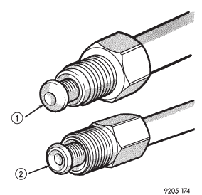
or twisting of metal brake tubes. Special flaring tools
are needed to make a double inverted flare or ISO
flare (Fig. 14). DOUBLE INVERTED FLARING (1) Cut off damaged tube with Tubing Cutter.
(2) Ream cut edges of tubing to ensure proper
flare.
(3) Install replacement tube nut on the tube.
(4) Insert tube in flaring tool.
(5) Place gauge form over the end of the tube.
(6) Push tubing through flaring tool jaws until
tube contacts recessed notch in gauge that matches
tube diameter.
(7) Tighten the tool bar on the tube
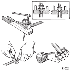
(8) Insert plug on gauge in the tube. Then swing
compression disc over gauge and center tapered flaring
screw in recess of compression disc (Fig. 15).
(9) Tighten tool handle until plug gauge is
squarely seated on jaws of flaring tool. This will start
the inverted flare.
1 - ISO-STYLE FLARE (10) Remove the plug gauge and complete the
inverted flare.
ISO FLARING To make a ISO flare use Snap-Ont Flaring Tool
TFM-428 or equivalent. (1) Cut off damaged tube with Tubing Cutter.
(2) Remove any burrs from the inside of the tube.
(3) Install tube nut on the tube. (4) Position the tube in the flaring tool flush with
the top of the tool bar (Fig. 16). Then tighten the tool
bar on the tube.
(5) Install the correct size adaptor on the flaring
tool yoke screw.
(6) Lubricate the adaptor.
(7) Align the adaptor and yoke screw over the tube
(Fig. 16).
(8) Turn the yoke screw in until the adaptor is
squarely seated on the tool bar.
1 - ADAPTERBrake fluid level

Fig. 11 Master Cylinder Fluid Level
2 - RESERVOIRMaster cylinder bleeding

Fig. 12 Master Cylinder Bleeding-Typical
2 - RESERVOIRBase brake bleeding

Fig. 13 Bleed Hose Setup
2 - FLUID CONTAINER PARTIALLY FILLED WITH FLUIDDisc rotor machining
Brake drum machining
Brake tube flaring

Fig. 14 Inverted Flare And ISO Flare
2 - DOUBLE INVERTED-STYLE FLARE
Fig. 15 Inverted Flare Tools
Fig. 16 ISO Flaring
2 - LUBRICATE HERE
3 - PILOT
4 - FLUSH WITH BAR
5 - TUBING
6 - BAR ASSEMBLY
Other materials:
Timing case cover. Timing chain and sprockets. Camshaft
Timing case cover
REMOVAL
(1) Disconnect battery negative cable.
(2) Remove accessory drive belt (Refer to Group
07, Cooling System for proper procedure)
(3) Remove the accessory drive brackets that are
attached to the timing case cover.
(4) Remove the fan and hub assembly and remove
the ...


